Shield connector

a shield shell and connector technology, applied in the direction of coupling device connection, coupling protective earth/shield arrangement, coupling device details, etc., can solve the problems of difficult to ensure the deformation of the tubular shield shell inwardly, etc., to reduce the diameter, the dimensional accuracy of the housing can be increased, and the effect of reducing the diameter

Inactive Publication Date: 2012-03-13
SUMITOMO WIRING SYST LTD
View PDF18 Cites 6 Cited by
  • Summary
  • Abstract
  • Description
  • Claims
  • Application Information

AI Technical Summary

Benefits of technology

[0008]The shield shell is deformed easily to reduce its diameter following the contraction of the housing during insert molding. Thus, the dimensional accuracy of the housing can be increased. Further, the opening preventing pieces contact to prevent opening of the shield shell.
[0009]The opening preventing piece may be at a position of the edge portion circumferentially projecting from the other part. Accordingly, the opposite edge portions facing each other with the cut therebetween are separated with the pair of opening preventing pieces held in contact, and the shield shell is deformed to reduce its diameter while narrowing the width of the cut of the shield shell as the housing contracts during insert molding. Thus, the opposite edge portions of the cut are not likely to contact when the shield shell is deformed to reduce its diameter, and a smooth deformation can be realized.

Problems solved by technology

However, the swaged tubular shield shell is difficult to deform inwardly following the contraction of the resin.
Thus, dimensional accuracy of the housing has been difficult to ensure.

Method used


Image

  • Shield connector
  • Shield connector
  • Shield connector

Examples


Embodiment Construction

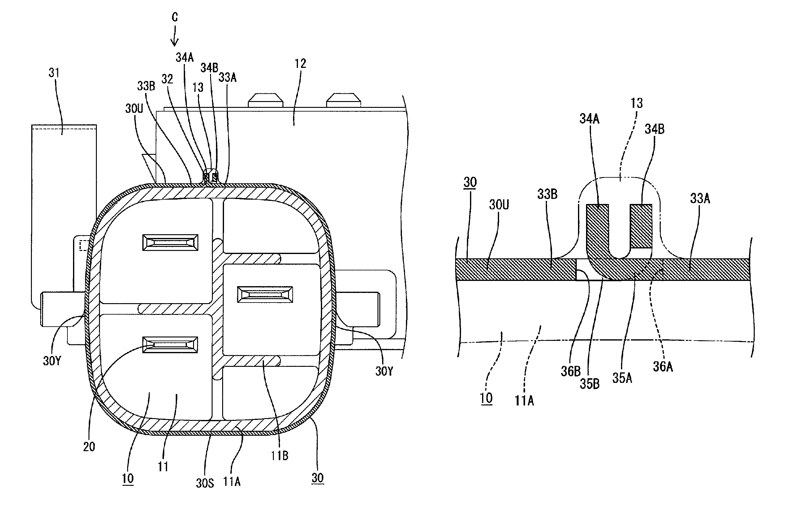
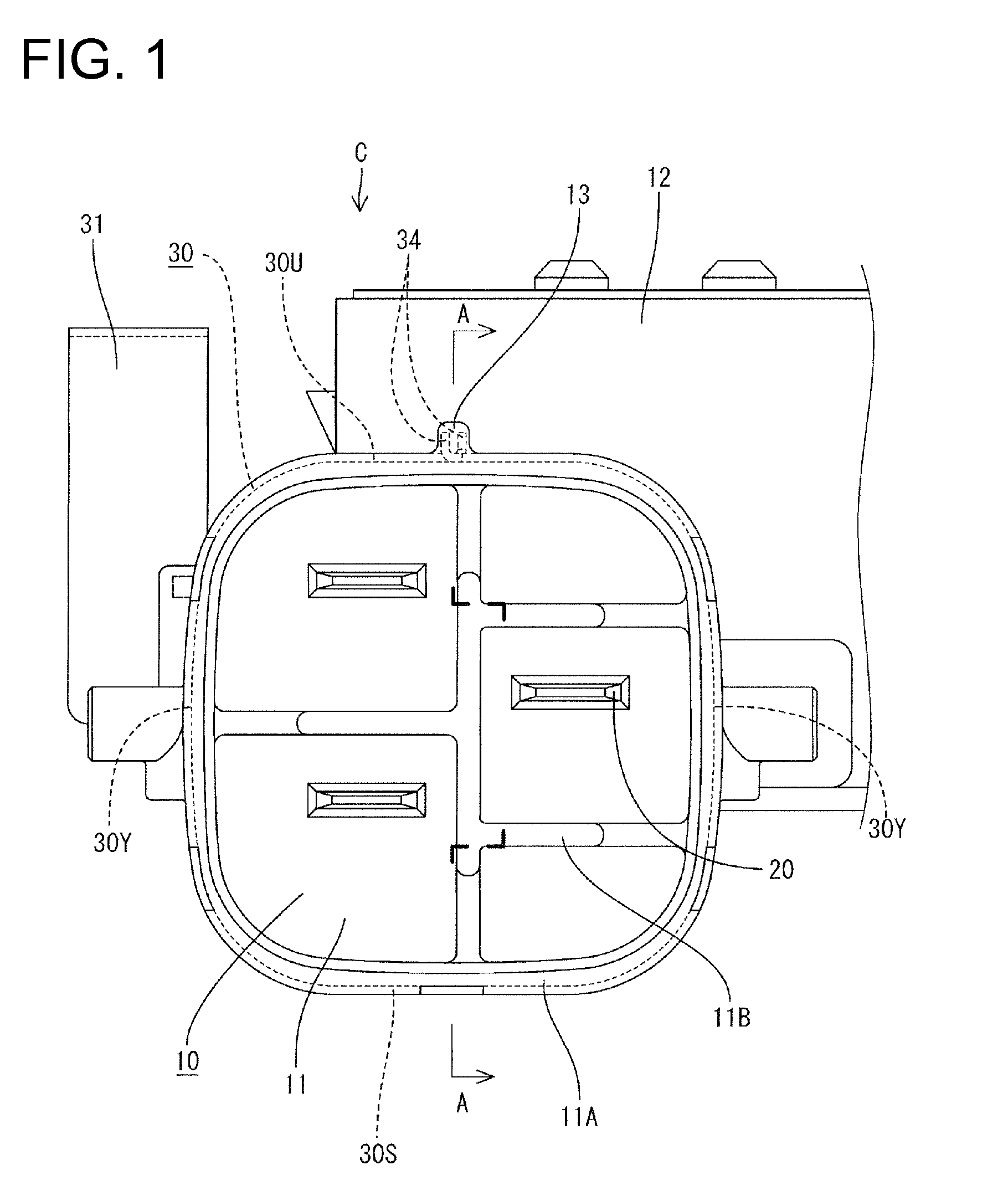
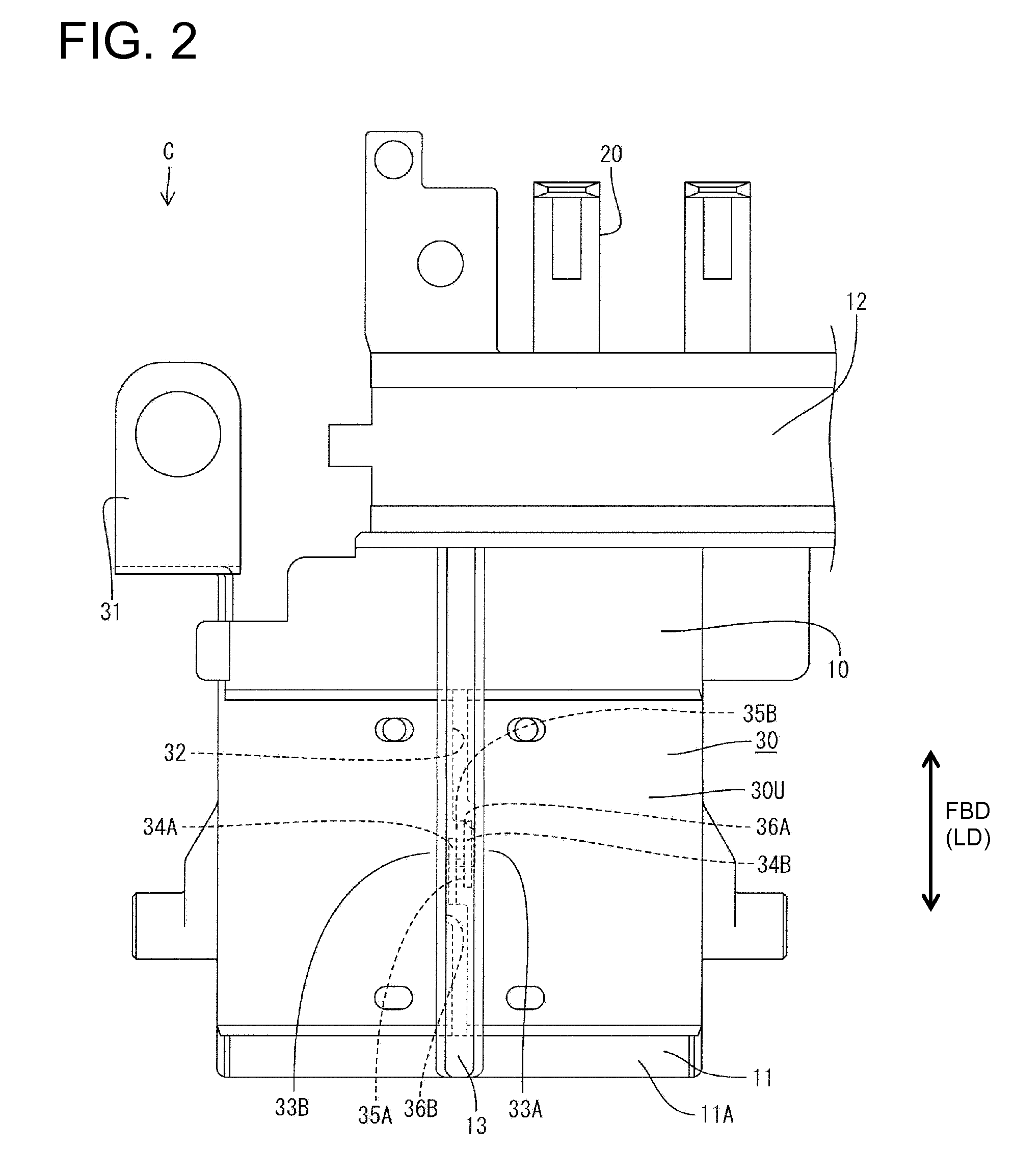
[0027]A shield connector in accordance with the invention is identified generally by the letter C and is configured to be mounted on a shield case (not shown) of a device, such as a motor of an electric car, and connected electrically to the device (not shown). In the following description, an end (lower end in FIG. 2) of each constituent element to be connected with an unillustrated mating connector is referred to as the front, and upper and lower ends of FIG. 1 are referred to as upper and lower ends.

[0028]The shield connector C is provided with a housing 10 made e.g. of synthetic resin, terminals 20 and a shield shell 30.

[0029]The housing 10 includes a fittable portion 11 configured to fit to the mating connector and at least one connector fixing portion 12 to be fixed to the shield case. The fittable portion 11 projects substantially forward from the connector fixing portion 12. The fittable portion 11 includes a forwardly open tube 11A and a partition 11B projecting forward in ...


PUM


Abstract

A shield connector (C) includes a tubular metallic shield shell (30) integrally attached to the outer circumferential surface of a housing (10) made of resin by insert molding. The shield shell (30) is formed with a cut (32) extending between opposite ends in a longitudinal direction, and a pair of opening preventing pieces (34A, 34B) which extend radially inward or outward, circumferentially face each other and can come into contact with each other when edges (33A, 33B) at the opposite sides of the cut (32) are displaced in directions away from each other are provided on the opposite edges (33A, 33B) of the shield shell 30 facing each other with the cut (32) therebetween.

Description

BACKGROUND OF THE INVENTION[0001]1. Field of the Invention[0002]The invention relates to a shield connector.[0003]2. Description of the Related Art[0004]Japanese Unexamined Patent Publication No. 2006-196198 discloses a shield connector with a tubular metallic shield shell integrally attached to the outer peripheral surface of a resin housing by insert molding. A shield member of a mating shield connector is connected with the outer peripheral surface of the shield shell.[0005]The above-described shield connector is produced by swaging a shield shell into a tubular form, setting the shield shell in a mold and then pouring resin into the mold. The mold is set to have a slightly larger size in anticipation of a contraction of the resin during insert molding. However, the swaged tubular shield shell is difficult to deform inwardly following the contraction of the resin. Thus, dimensional accuracy of the housing has been difficult to ensure.[0006]The invention was developed in view of t...

Claims


Application Information

Patent Timeline
Patent Type & Authority Patents(United States)
IPC IPC(8): H01R13/648
CPCH01R13/648H01R43/24H01R13/504
Inventor OKAMOTO, MASAKI
Owner SUMITOMO WIRING SYST LTD
Why Eureka
Try Eureka