Cage for roller bearing

a cage and roller bearing technology, applied in the direction of rotary bearings, shafts and bearings, rolling contact bearings, etc., can solve the problems of large roller-pushing load, inability to easily insert inability to so as to improve the ability of incorporating cages and rollers into outer rings, prevent the deformation of roller retaining portions, and easy deformation

Inactive Publication Date: 2010-11-16
JTEKT CORP
View PDF19 Cites 7 Cited by
  • Summary
  • Abstract
  • Description
  • Claims
  • Application Information

AI Technical Summary

Benefits of technology

[0013]As described above, the concave groove is formed in the back surface of each pillar portion and back surfaces of the annular portions disposed respectively at the circumferentially opposite ends of each pillar portion, and the width of the concave groove is smaller than the width of the pillar portion, and the separation groove portions each separating the roller retaining portion and the annular portion from each other are formed respectively at the opposite sides of those portions of the concave groove disposed respectively at the opposite ends of the pillar portion, and extend respectively to the corresponding circumferentially-opposite side surfaces of the pillar portion. Therefore, the thickness of that portion of the pillar portion lying between each roller retaining portion and the corresponding annular portion is reduced, and the roller retaining portion and the annular portion are separated from each other by the separation groove portion. Therefore, the annular portions less prevent the deformation of the roller retaining portions, and the roller retaining portions can be more easily deformed, and therefore there is achieved an advantage that the ability of incorporating the cage and the rollers into an outer ring can be enhanced.
[0014]And besides, the separation groove portions are formed respectively at the opposite sides of those portions of the concave groove disposed respectively at the opposite ends of the pillar portion, and extend respectively to the circumferentially-opposite side surfaces of the pillar portion, and the separation groove portions are disposed respectively at corner portions of the pockets, and therefore a lubricating effect achieved by supply of grease or lubricant to the pockets receiving the respective rollers is enhanced.
[0015]Furthermore, the width-increasing groove portions are formed respectively at the opposite sides of those portions of the concave groove disposed respectively at the annular portions, and extend respectively beyond the circumferentially-opposite side surfaces of the pillar portion. Therefore, those portions of the annular portions having the width-increasing groove portions are reduced in thickness, and therefore the annular portions are reduced in rigidity, and therefore the annular portions having the width-increasing groove portions less affect the deformation of the roller retaining portions, so that the roller retaining portions can be more easily deformed.

Problems solved by technology

Therefore, when the rollers are pushed radially into the respective pockets, the roller retaining portions can not be easily deformed, and therefore a roller-pushing load becomes large.
As a result, the cage having the rollers set therein can not be easily inserted into the outer ring, and this phenomenon is conspicuous particularly when the number of the roller is large and when the sectional thickness of the cage is large.

Method used


Image

  • Cage for roller bearing
  • Cage for roller bearing
  • Cage for roller bearing

Examples


first embodiment

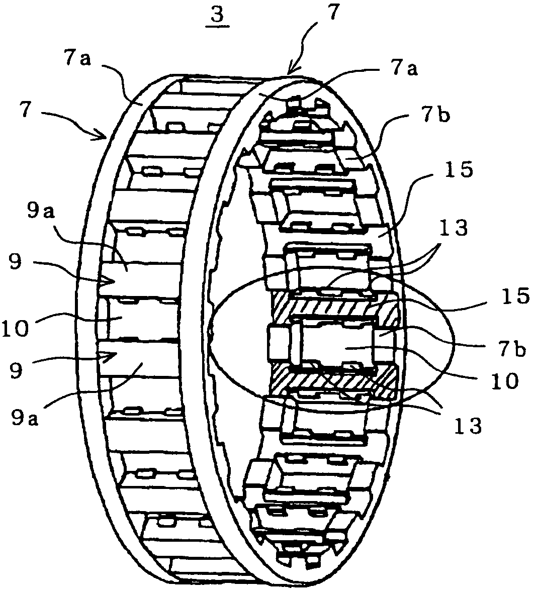
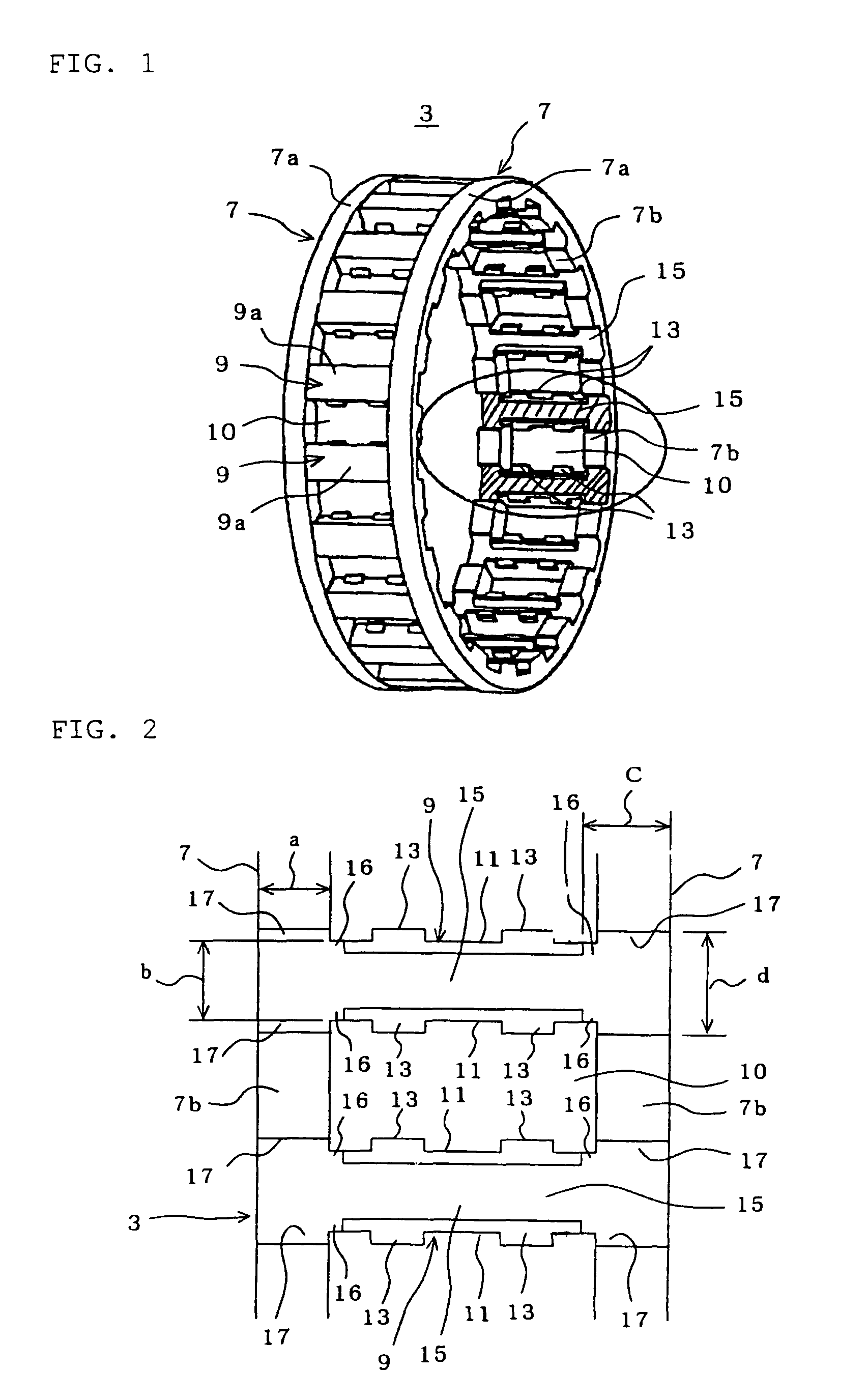
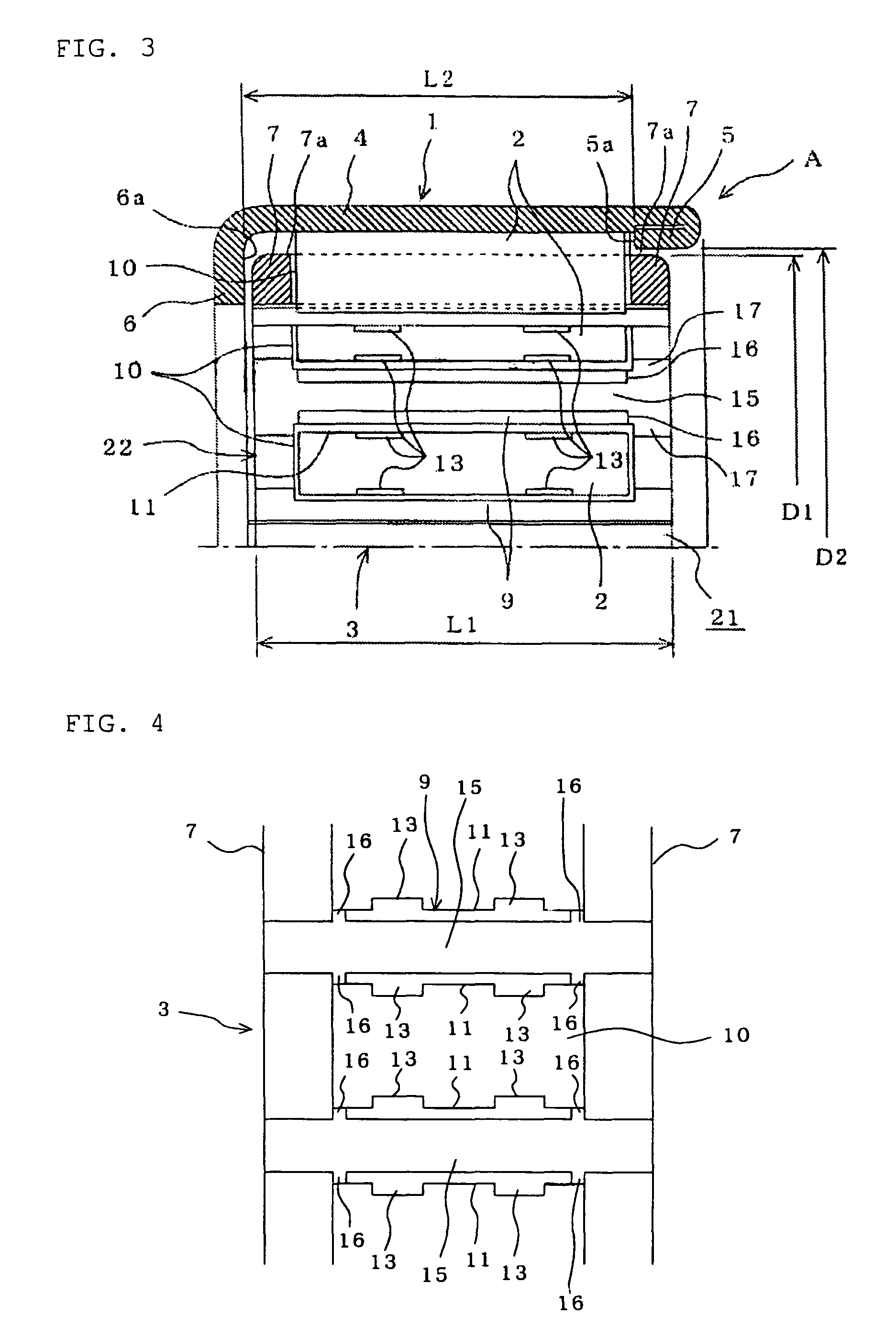
[0020]FIG. 1 is a perspective view of a first embodiment of a roller bearing cage of the present invention, FIG. 2 is a plan view of an important portion of the roller bearing cage as seen from a back surface-side thereof, and FIG. 3 is an enlarged partially cross-sectional view of a roller bearing provided with the roller bearing cage.

[0021]In these Figures, reference numeral 1 denotes a drawn cup outer ring, reference numeral 2 denote a needle roller, and reference numeral 3 denotes the roller bearing cage. The needle roller bearing A is formed by the outer ring 1, the needle rollers 2 and the cage 3.

[0022]The outer ring 1 includes a tubular raceway portion 4, and a pair of ribs 5 and 6 formed respectively at axially opposite ends of the raceway portion 4, and this outer ring 1 is formed into a one-piece construction. One rib 5 is smaller in thickness than the raceway portion 4, and is bent to be disposed contiguous to an inner peripheral surface of the raceway portion 4 over an e...

second embodiment

[0044]FIG. 4 is a plan view of an important portion of a second embodiment of a roller bearing cage of the invention as seen from a back surface-side thereof.

[0045]In the second embodiment of the invention shown in FIG. 2, those portions similar in construction to the corresponding portions of the first embodiment will be designated by identical reference numerals, respectively, and explanation thereof will be omitted.

[0046]In the first embodiment, the separation groove portions 16 and the width-increasing groove portions 17 are formed at the concave groove 15. In this second embodiment, however, only separation groove portions 16 are formed at each concave groove 15

[0047]Namely, the concave groove 15 is formed in each pillar portion 9 and annular portions 7, and in addition the separation groove portions 16 are formed respectively at opposite sides of those portions of the concave groove 15 disposed respectively at opposite ends of the pillar portion 9, and extend respectively to t...


PUM


Abstract

A roller bearing cage includes annular portions provided respectively at opposite ends thereof, a plurality of pillar portions interconnecting the annular portions, a plurality of pockets for respectively holding needle rollers, and roller retaining portions formed respectively on circumferentially-opposed wall surfaces and of each pocket portion. A concave groove smaller in width than the pillar portion is formed axially in a back surface of each pillar portion and those portion of back surfaces of the annular portions disposed respectively at opposite ends of each pillar portion. Separation groove portions are formed respectively at opposite sides of those portions of the concave groove disposed respectively at the opposite ends of the pillar portion, and extend respectively to corresponding circumferentially-opposite side surfaces of the pillar portion, and each separation groove portion separates the corresponding roller retaining portion and annular portion from each other.

Description

FIELD OF THE INVENTIONBackground of the Invention[0001]This invention relates to a roller bearing cage for locating and rollably holding a plurality of rollers at an inner periphery of an outer ring.[0002]A conventional cage for a roller bearing includes a pair of annular portions provided respectively at opposite ends thereof, a plurality of pillar portions interconnecting these annular portions, and a plurality of pockets formed between the pillar portions so as to respectively hold rollers. Roller retaining portions are formed on radially-inward portions of wall surfaces of the pockets, and deformation-allowing portions each in the form of a concave groove are formed respectively in back surfaces of the pillar portions, and extend in an axial direction of the cage. When the roller retaining portions are pressed by the rollers, each deformation-allowing portion allows the corresponding pillar portion to be elastically deformed in this pressing direction, and when this pressing is ...

Claims


Application Information

Patent Timeline
Patent Type & Authority Patents(United States)
IPC IPC(8): F16C33/54F16C19/26
CPCF16C19/466F16C33/4635F16C33/467F16C19/26F16C2240/40F16C33/4676F16C2300/02
Inventor HASHIMOTO, KENICHI
Owner JTEKT CORP
Why Eureka
Try Eureka