Simplified fabrication method of toroidal charged particle deflector vanes

a fabrication method and technology of toroidal charge, applied in the manufacture of electrode systems, resistive material coating, electric discharge tubes/lamps, etc., can solve the problems of difficulty and time involved in winding the form to make the coils

Inactive Publication Date: 2002-10-08
NIKON CORP
View PDF5 Cites 5 Cited by
  • Summary
  • Abstract
  • Description
  • Claims
  • Application Information

AI Technical Summary

Benefits of technology

It is another object of the invention to provide a method for fabricating high precision, thermally stable electromagnetic coil vanes that does not require specialized tooling to align and clamp the copper coils.
It is yet another object of the present invention to provide a method for fabricating high precision, thermally stable electromagnetic coil vanes that does not require the use of a bonding composition to bond the copper coils to the substrate.
According to the invention, a method is provided to fabricate high current capacity, high accuracy, thermally stable deflection yokes used to generate off axis beam deflections.

Problems solved by technology

As the number of radially cut grooves and the number of turns increases, so does the degree of difficulty and the time involved for winding the form to make the coils.

Method used


Image

  • Simplified fabrication method of toroidal charged particle deflector vanes
  • Simplified fabrication method of toroidal charged particle deflector vanes
  • Simplified fabrication method of toroidal charged particle deflector vanes

Examples


Embodiment Construction

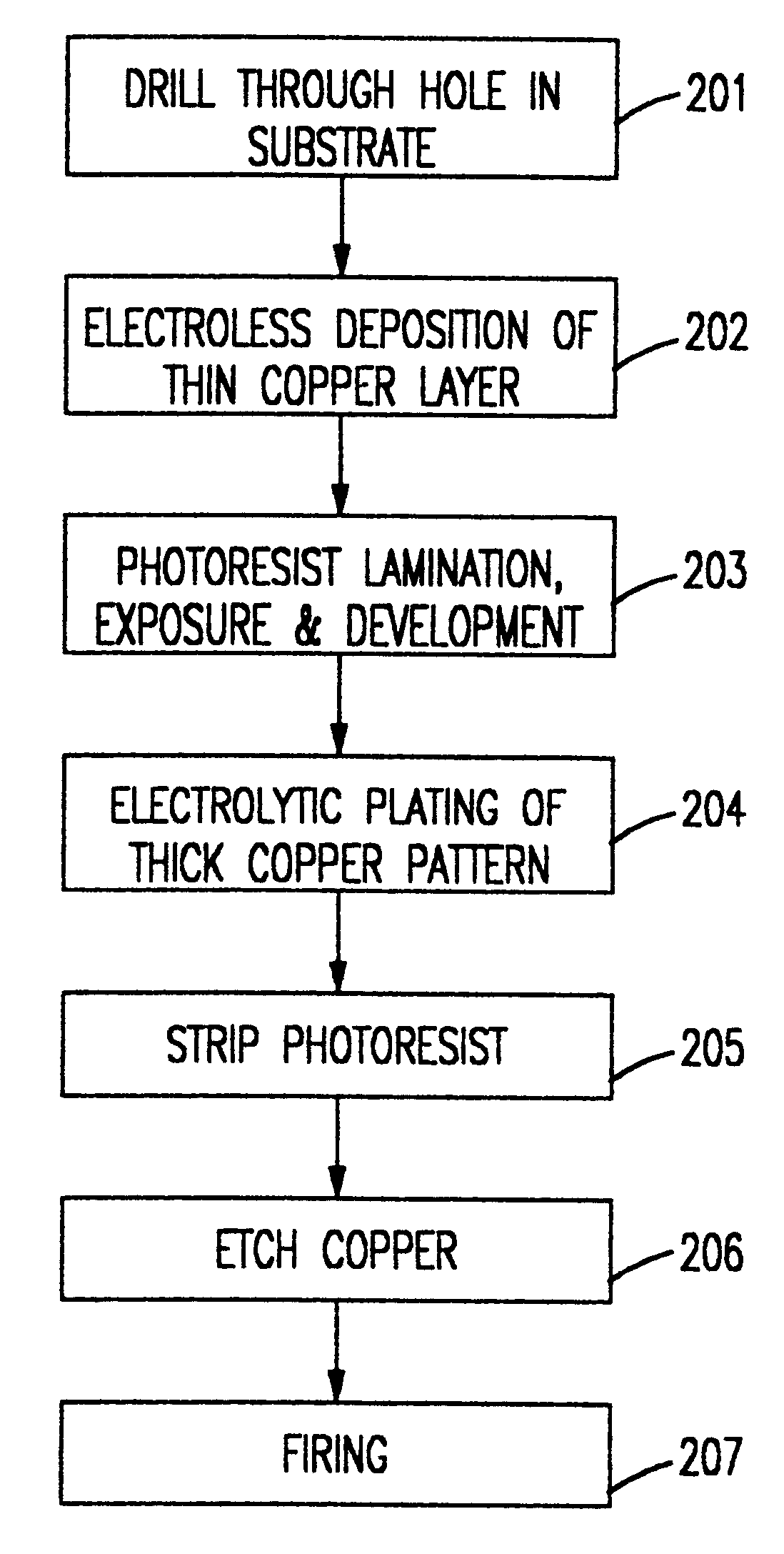
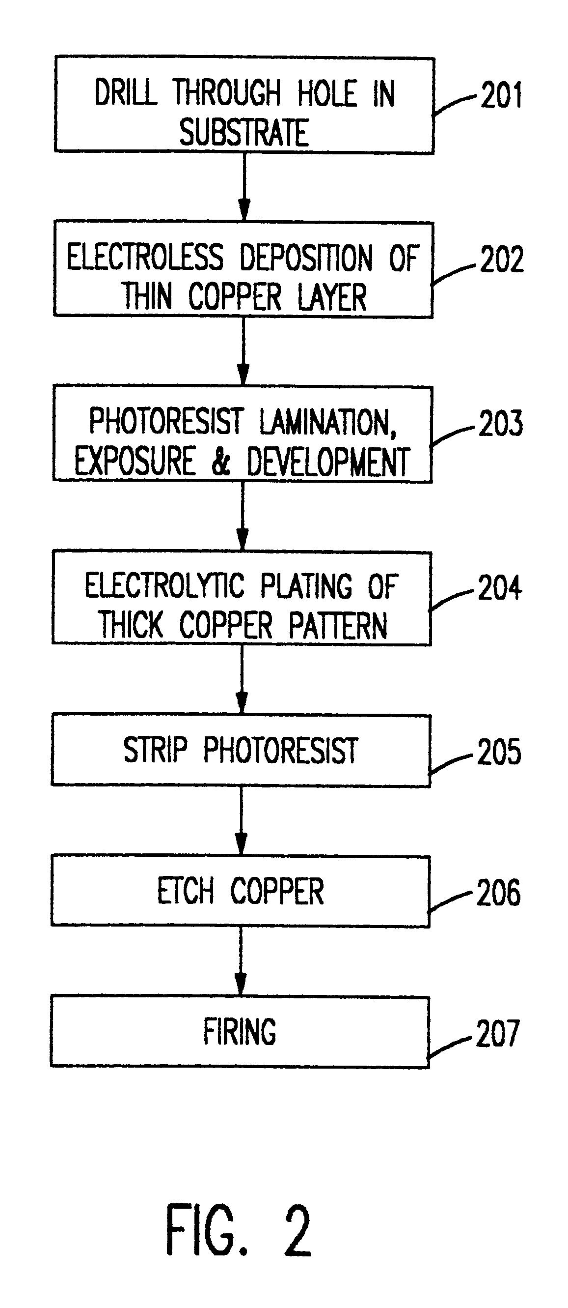
Referring now to the drawings, and specifically to FIG. 2, a flowchart is provided for the present process. Beginning with step 201, a through hole 400 is drilled through substrate 303, which provides an electrical connection between coil patterns 301 and 302. Drilling is preferably done in either the conventional manner or by laser action. The substrate 303 preferably has a low coefficient of thermal expansion (CTE). For example, in a preferred embodiment, any particular ceramic can be used that has a CTE of approximately 7.times.10.sup.-6 / .degree. C. Other wires and substrates may also be used with the present invention, depending on the particular application. For example, Zerodur.RTM., produced by Schott Glaswerke (Mainz, Germany) may also be used as a substrate.

At step 202, a thin layer of copper 401 is deposited over the entire surface of the substrate 303 and in the through hole 400 by electroless deposition. This step is necessary to create a conductive layer on the substra...


PUM

PropertyMeasurementUnit
thicknessaaaaaaaaaa
thicknessaaaaaaaaaa
temperatureaaaaaaaaaa

Abstract

The present invention relates to a method and apparatus of fabricating electromagnetic coil vanes. The method involves photolithographically exposing high resolution, dense wire patterns in a flash coat of copper, on both sides of a ceramic vane substrate. The substrate can be pre-drilled with a through hole to connect the two copper coil patterns. Additional copper is then deposited on both high resolution patterns and in the through hole by plating until the desired thickness is obtained. A firing operation is then performed that eutectically bonds the copper to the ceramic.

Description

DESCRIPTION1. Field of the InventionThe present invention generally relates to Charged Particle Beam Projection Systems, and more particularly, to a method for fabricating high precision, thermally stable electromagnetic coil vanes used with Charged Particle Beam Projection Systems.2. Background DescriptionYokes and electromagnetic lenses are widely used in charged particle beam tools such as electron beam tools, electron microscopes, and cathode ray tubes and ion beam systems. Yokes and lenses employing toroidal magnetic deflection coils are commonly used in electron beam lithography systems for focusing an electron beam onto a substrate for submicron patterning of semiconductor devices.U.S. Pat. No. 4,251,728 to Pfeiffer shows an example of a toroidal magnetic deflection yoke. FIG. 1 shows a top view of a traditional toroidal yoke similar to that shown in Pfeiffer. The traditional yoke includes a plastic form having slots numbered from 1 to 20, and forms both X and Y coil axes.Pre...

Claims


Application Information

Patent Timeline
Patent Type & Authority Patents(United States)
IPC IPC(8): C23C18/16C23C26/00H01J9/00H01J9/236H05K3/42H05K1/03H05K3/10G03F7/20H01F41/04H01J37/147H01J37/305H01L21/027
CPCC23C26/00H01J9/236H05K3/426C23C18/1605H01J2237/152Y10T29/49117H05K3/108H05K1/0306
Inventor PINCKNEY, DAVID J.
Owner NIKON CORP
Why Eureka
Try Eureka