Micropower RC oscillator

a micro-power, rc oscillator technology, applied in the direction of logic circuit coupling/interface arrangement, pulse technique, instruments, etc., can solve the problems of complex circuit configuration, large resulting rc oscillator, complicated manufacturing process of rc oscillator,

Inactive Publication Date: 2002-10-08
SAMSUNG ELECTRONICS CO LTD
View PDF6 Cites 66 Cited by
  • Summary
  • Abstract
  • Description
  • Claims
  • Application Information

AI Technical Summary

Problems solved by technology

At this time, it is common to arrange the resistor R external to the chip for the oscillation frequency to have an individual relation with chip manufacturing process errors and to control the value of the resistor R. Accordingly, the manufacturing process of the RC oscillator becomes more complicated and the resulting RC oscillator is larger.
However, the RC oscillator requires a complicated circuit configuration to provide such functions.
In some cases, the voltage level of the oscillation frequency obtained from the RC oscillating circuit does not meet the voltage level required from a receiving end.

Method used


Image

  • Micropower RC oscillator
  • Micropower RC oscillator
  • Micropower RC oscillator

Examples


Embodiment Construction

A description of the preferred embodiments will now be provided in detail with reference to the accompanying drawings.

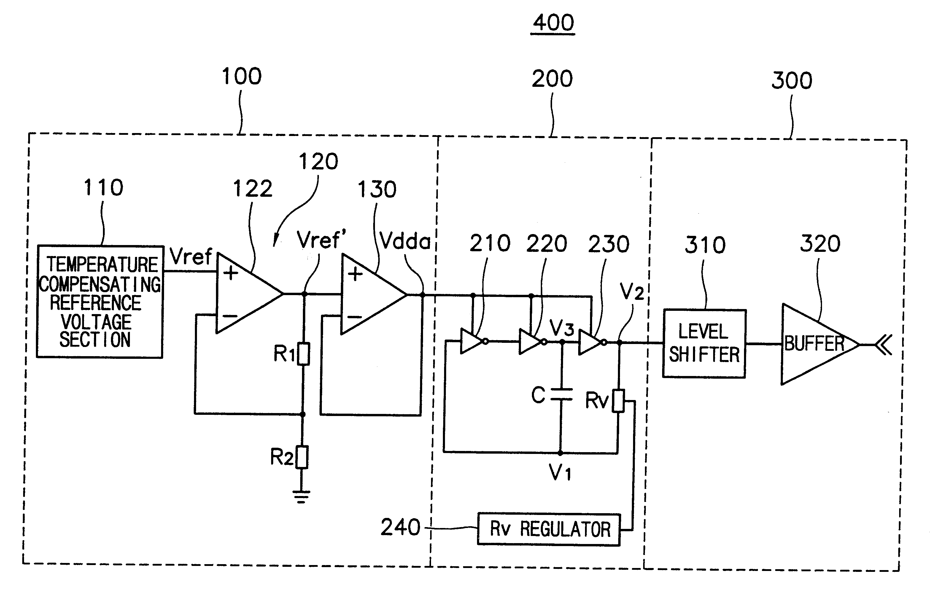
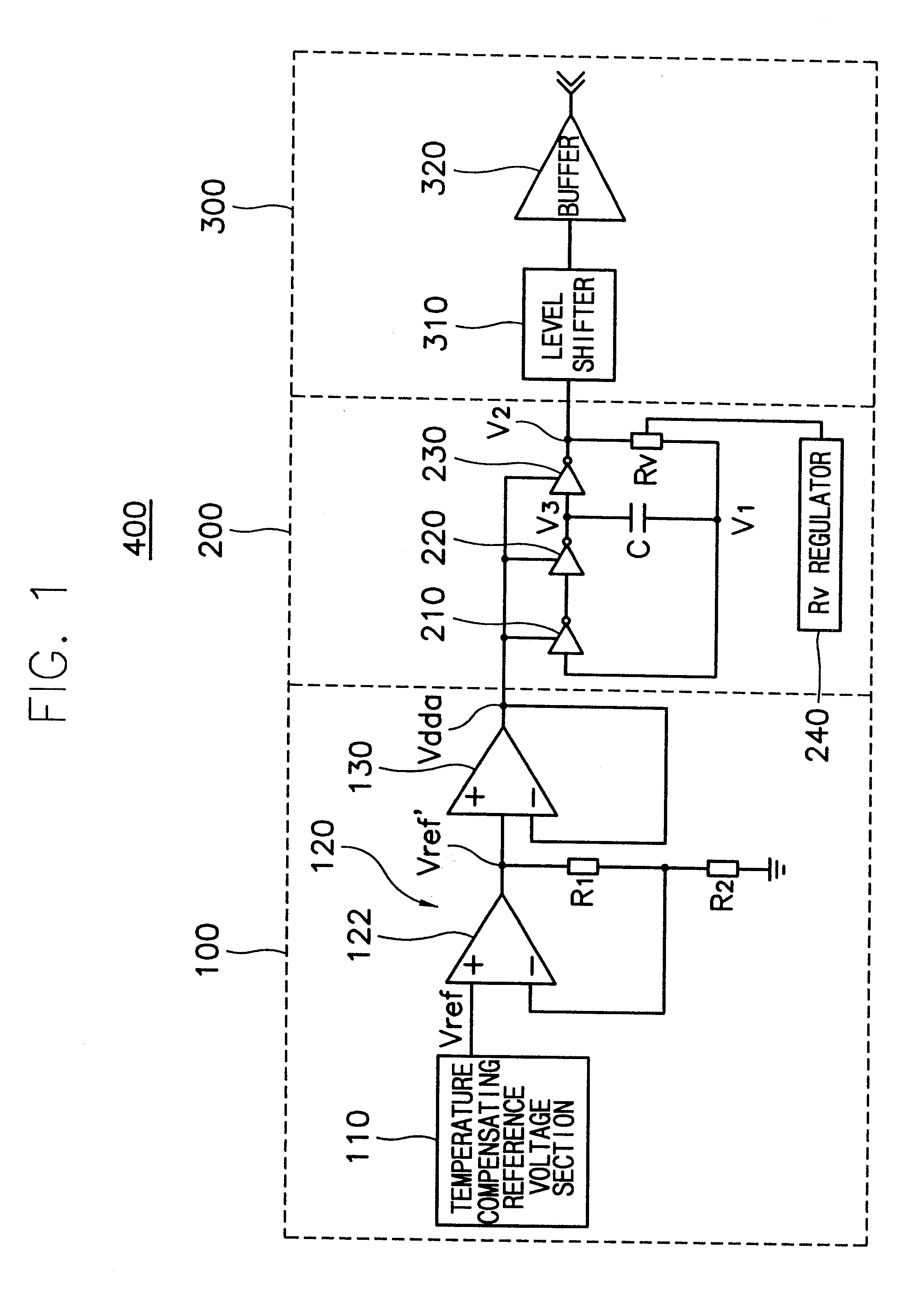
FIG. 1 depicts a circuit configuration of a micropower RC oscillator 400 according to a first preferred embodiment of the present invention. The micropower RC oscillator 400 includes a driving voltage circuit 100 and an RC oscillation circuit 200.

The RC oscillation circuit 200 controls a capacitor C to be repeatedly charged and discharged with a frequency decided by a time constant of an RC circuit. The RC circuit includes a plurality of inverter circuits connected in series and driven by the driving voltage supplied from the driving voltage circuit 100, a resistor and a capacitor to output a voltage waveform oscillated by the frequency into an output stage. Particularly, the RC oscillation circuit 200 includes a plurality of inverters, for example three inverters 210, 220 and 230. The three inverters 210, 220 and 230 are connected to the output stage of the driving ...


PUM


Abstract

A micropower RC oscillator having stable frequency characteristics with varying temperature includes a number of inverting circuits which are driven by an external driving voltage and connected in series with each other and an RC circuit having a resistor disposed in between a head-inverter and a tail inverter to form a closed loop and a capacitor disposed between the tail-inverter and the head-inverter. The resistor comprises a plurality of unit resistors constituting of a P+ diffusion resistor and a polysilicon resistor having opposing characteristics with respect to temperature variation at a predetermined ratio. A resistance regulator controls the resistance of the resistor by decoding an external resistance setting data to select a unit resistor that determines the oscillation frequency effectively. A driving voltage circuit receives a reference signal having the voltage level which is stable against the temperature variation by using a current source and a load having opposing characteristics with respect to the temperature variation and provides as a driving voltage of the RC oscillating circuit after increasing a fan-out capacity of the reference signal. An output level shifting circuit can be added to the rear side of the RC oscillating circuit to adjust the voltage level of the oscillation signal with the appropriate standard required at a receiving end.

Description

1. Field of the InventionThe present invention relates to an oscillating circuit, and more particularly to a low power micropower RC oscillator that has stable oscillation frequency characteristics with varying temperature and capable of variably changing oscillation frequency by adjusting a resistance value.2. Description of the Related ArtOscillating circuits are commonly used as devices for providing a clock signal or a timing signal to electronic circuits such as a micro-processor, a micro-controller, a flip-flop circuit and a latch circuit. They are widely applied in industrial electronics. A crystal oscillating circuit provides an accurate and stable reference frequency.However, in many applications, such a high-quality reference frequency is not required and since a mass productivity should be considered, an RC-type oscillator can be used as a low-cost clock signal source or a timing signal source. Also, an RC oscillator generates a variable frequency by changing the resistan...

Claims


Application Information

Patent Timeline
Patent Type & Authority Patents(United States)
IPC IPC(8): H03B5/00H03B5/04G05F3/24H03B5/20H03K3/354H03K19/0185
CPCH03B5/04
Inventor KIM, GYEONG-NAM
Owner SAMSUNG ELECTRONICS CO LTD
Why Eureka
Try Eureka