Modular thermoelectric unit and cooling system using same

a module-type thermoelectric unit and cooling system technology, applied in the field of module-type thermoelectric units, can solve the problems of unit requiring a circulation system and coolant reservoir, unit frequently leaking, and requiring extensive and costly preventive maintenan

Inactive Publication Date: 2002-10-15
LALIBERTE JACQUES
View PDF11 Cites 94 Cited by
  • Summary
  • Abstract
  • Description
  • Claims
  • Application Information

AI Technical Summary

Benefits of technology

FIG. 7 is a schematic block diagram of a supply/control unit used in co-operation with modular thermoele

Problems solved by technology

This is particularly true in the case of movable commercial apparatuses where fluid leakage frequently occurs requiring extensive and costly preventive maintenance.
However, use of thermoelectric units has never been contemplated in large refrigerating units such as grocery store refrigerators and coolers.
Of those that are assembled as complete stand-alone units, these are not designed for easy installation on an insulated wall and removal therefrom as one or more complete units.
As disclosed, the cooling unit requires a coolant reservoir and circulation system, cannot be easily retrofitted into an existing refrigeration apparatus and is complex and expensive to manufacture.
It provides local cooling and was not designed in a manner allowing the co-operative use of multiple units to provide uniform cooling throughout the entire volume of a large refrigerating e

Method used


Image

  • Modular thermoelectric unit and cooling system using same
  • Modular thermoelectric unit and cooling system using same
  • Modular thermoelectric unit and cooling system using same

Examples


Embodiment Construction

Similar parts in the various figures of the appended drawings are identified by the same reference numerals.

Illustrative embodiments of the modular thermoelectric cooling unit according to the present invention will now be described in detail with reference to the appended drawings.

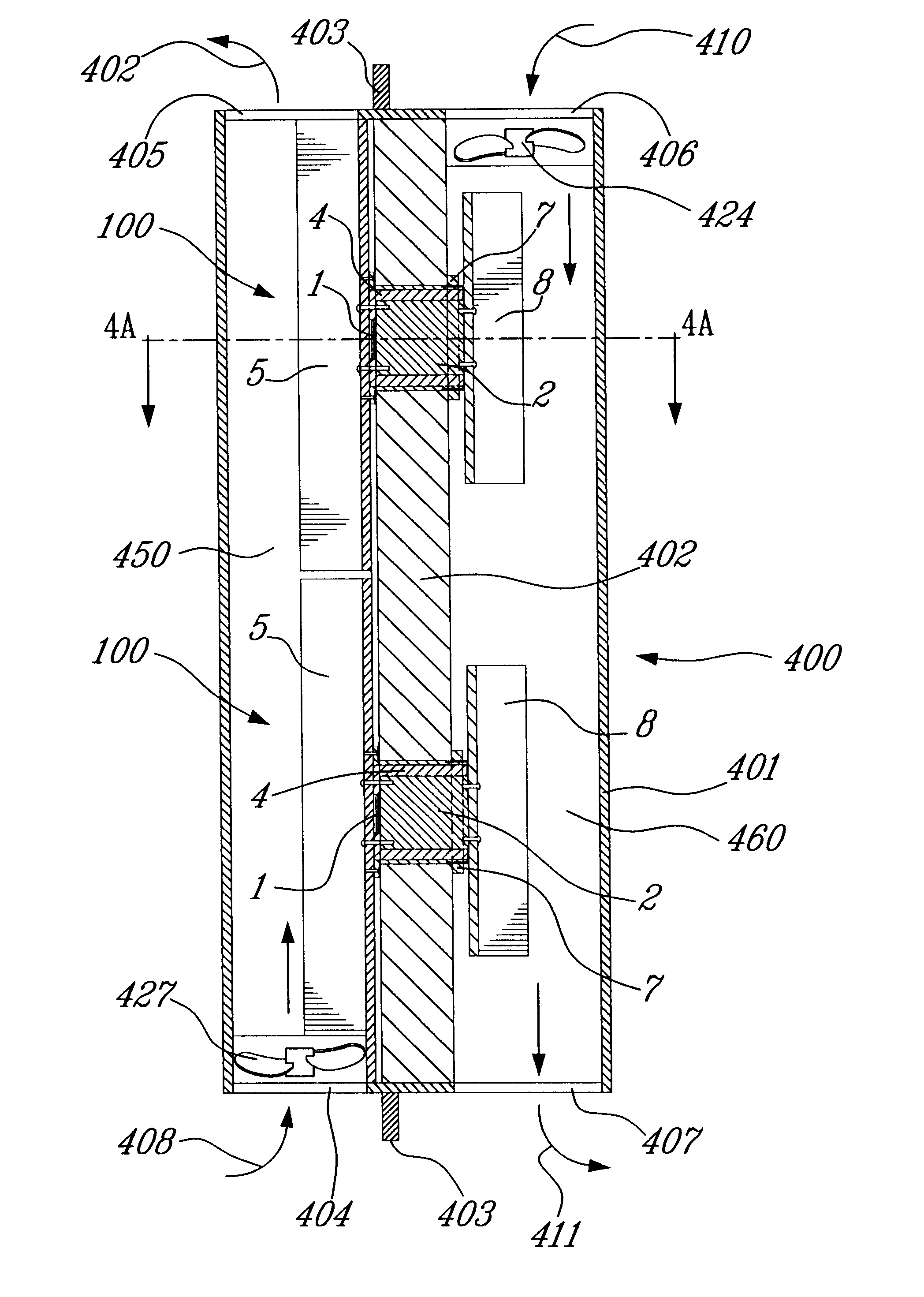
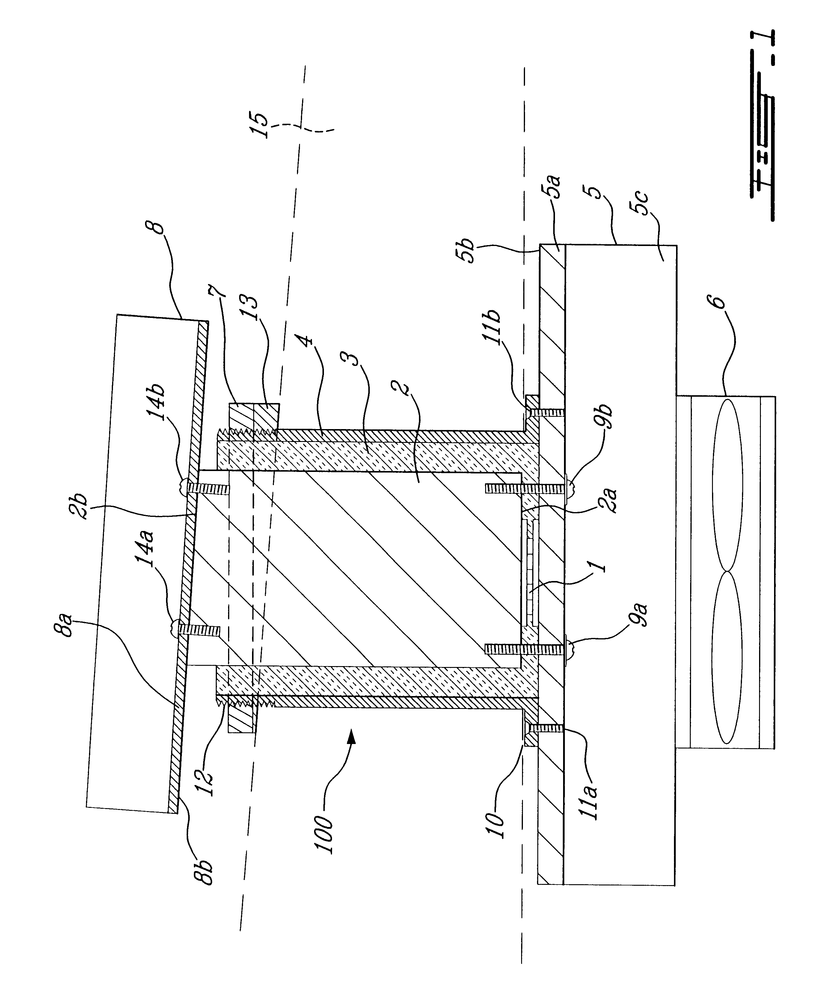
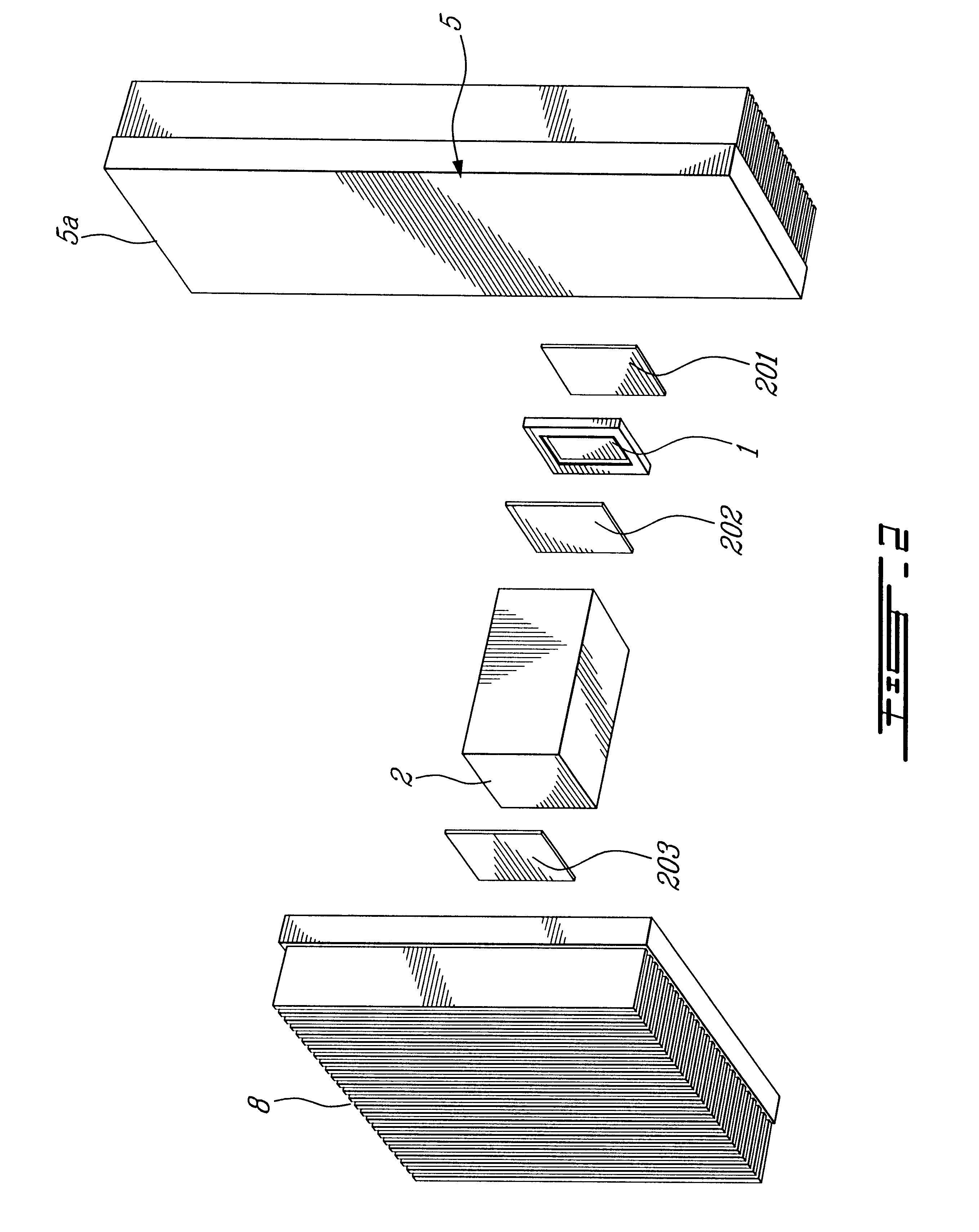
Referring to FIG. 1, there is illustrated a modular thermoelectric cooling / heating unit generally identified by the reference 100 and comprising a TEC device 1 sandwiched between a finned heatsink 5 and a heat conducting block 2.

Since TEC devices normally have hot and cold side square surfaces, optimal thermal transfer occurs when the end face of heat conducting block 2 facing the TEC device 1 has substantially the same shape and size. Therefore, a heat conducting block 2 with a square cross section can be considered. However, optimal thermal transfer also requires the cross section of heat conducting block 2 to be generally larger than the cross section of the hot or cold surface of the TEC device 1. It ...


PUM


Abstract

A modular thermoelectric cooling/heating unit is installed through an opening in a wall separating first and second temperature zones. This modular thermoelectric cooling/heating unit comprises a thermoelectric device including a cold surface, a hot surface, and a cooling/heating member between an electrical power supply and the cold and hot surfaces. A heat conducting block has a proximal end for thermally contacting with a first one of the cold and hot surfaces, and a distal end. A first heatsink thermally contacts with a second one of the cold and hot surfaces, a second heatsink thermally contacts with the distal end of the heat conducting block, and a thermally insulated housing covers at least a portion of the heat conducting block between the proximal and distal ends of this block. In operation, the first heatsink is located in the first temperature zone, at least a portion of the heat conducting block and the thermally insulated housing extend through the wall opening, and the second heatsink is located in the second temperature zone. The above described modular thermoelectric cooling/heating unit can be used in a modular cooling system for retrofit into an existing refrigeration unit.

Description

The present invention relates to a thermoelectric unit for the cooling or heating of a fluid. This thermoelectric unit can be installed through an opening in a wall and is suited, in particular but not exclusively, for providing cooling for a refrigerating apparatus.In thermoelectric systems, one or more flat board like semiconductor devices generally known as thermoelectric coolers (TECs) transfer heat according to the Peltier effect. A direct electrical current is applied to the semiconductor device which results in a corresponding transfer of heat from one side of the semiconductor device to the other, thereby creating a cold side and a hot side.TEC based thermoelectric systems address environmental concerns given the complete absence of a requirement for the use of heat transfer fluids such as Freon.TM., required in more conventional evaporating / condensing type units, while at the same time providing a lighter, more reliable and potentially less expensive apparatus. Moreover, TE...

Claims


Application Information

Patent Timeline
IPC IPC(8): F25B21/04F25B21/02H01L35/28H01L35/30F25D11/00
CPCF25B21/04H01L35/30F25B2321/0212F25B2321/023F25B2321/0251F25D11/00H10N10/13
Inventor LALIBERTE, JACQUES
Owner LALIBERTE JACQUES
Why Eureka
Try Eureka