Check patentability & draft patents in minutes with Patsnap Eureka AI!

Surface temperature sensor head

a surface temperature and sensor head technology, applied in the direction of instruments, heat measurement, thermoelectric devices, etc., can solve the problems of inability of the thermocouple to measure temperature at a plurality of spots, inability to move the sensing part accompanies the thermistors, and inability to achieve thermal equilibrium

Inactive Publication Date: 2002-10-15
SUMITOMO ELECTRIC IND LTD
View PDF15 Cites 21 Cited by
  • Summary
  • Abstract
  • Description
  • Claims
  • Application Information

AI Technical Summary

Benefits of technology

Enables high-resolution, non-destructive temperature measurement at multiple spots with improved thermal equilibrium, enhancing the accuracy and speed of thermal analysis for LDs and LSIs, while maintaining the integrity of the object being tested.

Problems solved by technology

It is difficult for the thermocouple to measure temperature at a plurality of spots on an object because of the difficulty of moving the tip.
The difficulty of moving a sensing part accompanies the thermistors.
If the tip of the thermocouple is bluntly pushed to the object without the copper disc, unstable air gaps existing between the tip and object suppress heat conduction, inhibit thermal equilibrium and forbid the sensor to measure the exact temperature of the object.
Even a touch of a very thin needle induces extra heat conduction which disturbs the temperature of the wafer.
However, the temperature of the wafer is not necessarily equal to the temperature of the stage.
However, drawbacks plague these proposals.
When the sample is a composition of metal and glass, the components have different radiation rates and infrared light scattered by the metal surface induces external noise.
The difference of radiation rates and the induced noise disturb the operation of the radiation thermometer.
The carbon coating cannot be eliminated.
Another drawback appears in the case of samples having steps on the surface.
Defocus of the microscope impairs spatial resolution of the temperature distribution.
Because of the brazing, non-destructive measurement is difficult for the chip thermistor or the platinum temperature measuring resistor.
The resistor sensors are inappropriate for simultaneous measurement of a plurality of spots by several chips.
Fragility causes inconvenience of maintenance.
The measurement by thermocouples has also problems.
Non-destructive measurement is difficult for the thermocouple.
However, such a sensor is inapt for measuring temperature at different spots on an object.
Besides, another problem should be pointed out for the thermocouple making use of a kind of heat sink, for example, a copper disc.
The large heat sink hinders the thermocouple in measuring temperature distribution of narrow regions on the sample.
Furthermore, the large heat sink deprives the sample of heat, which perturbs the thermal equilibrium.
However, it is difficult to fix a small copper disc to the tip of a thermocouple.
These difficulties accompany the Cu-carrying thermocouples.
It is inappropriate for determining temperature distribution which requires temperatures at a plurality of spots.
The production of the hemisphere requires difficult processing of boring a microhole in the copper ball and cutting the Cu ball into hemispheres.
In particular, it is difficult to finish a tiny copper ball of a diameter of less than 0.8 mm.
On the other hand, the copper head is so big that it is difficult to investigate micro-distribution of temperature of the object having a complex surface structure.
Further, it is difficult to investigate micro-distribution on the surface.
Poor heat capacitance of the thin tip would bring about only unstable contact with the object, if a naked tip were in contact with the object.
Too large heat capacitance is undesirable for the plates.

Method used


Image

  • Surface temperature sensor head
  • Surface temperature sensor head
  • Surface temperature sensor head

Examples


embodiment 1 (two independent discs ; fig.3 , fig.4)

[Embodiment 1 (Two Independent Discs; FIG. 3, FIG. 4)]

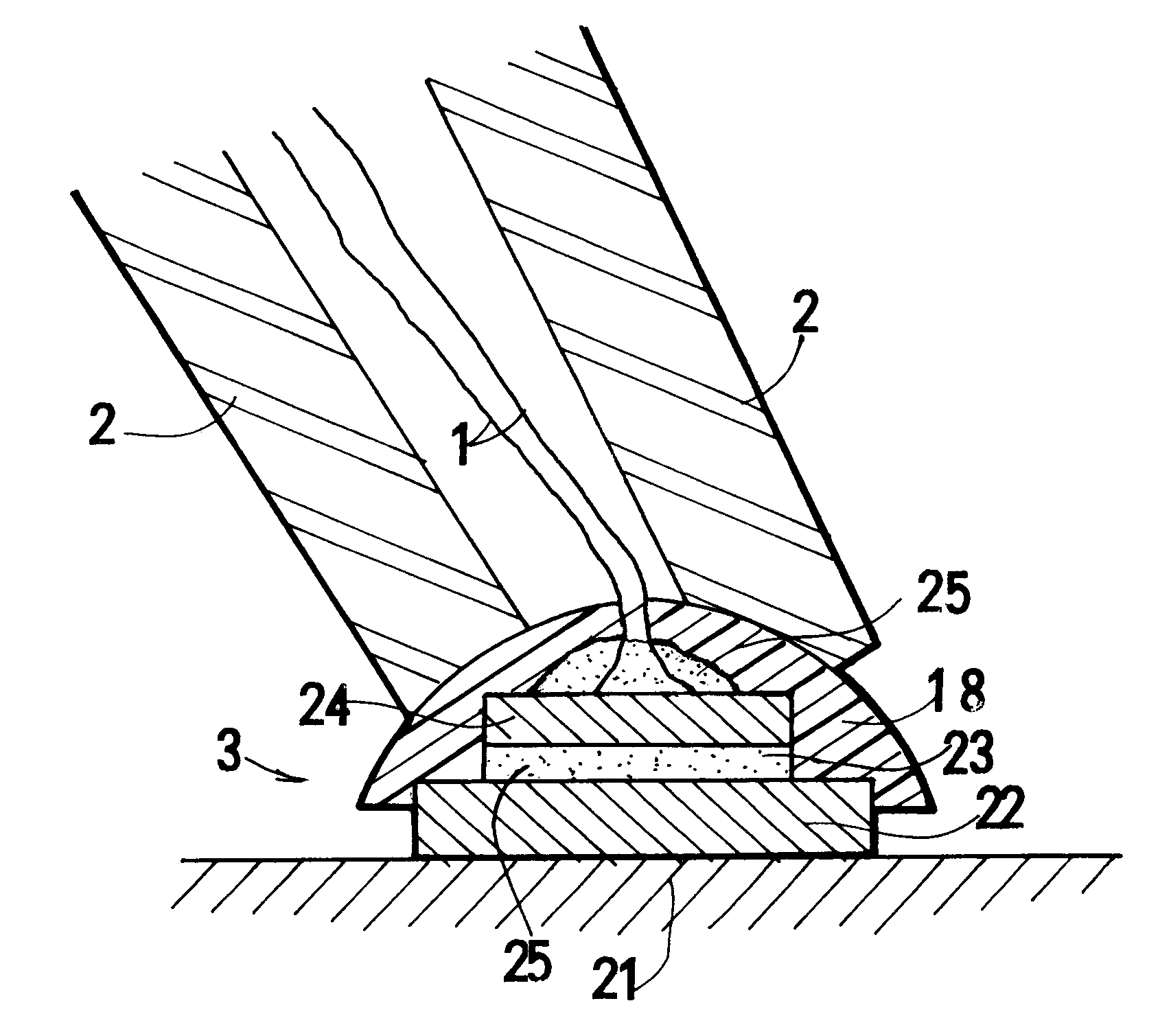
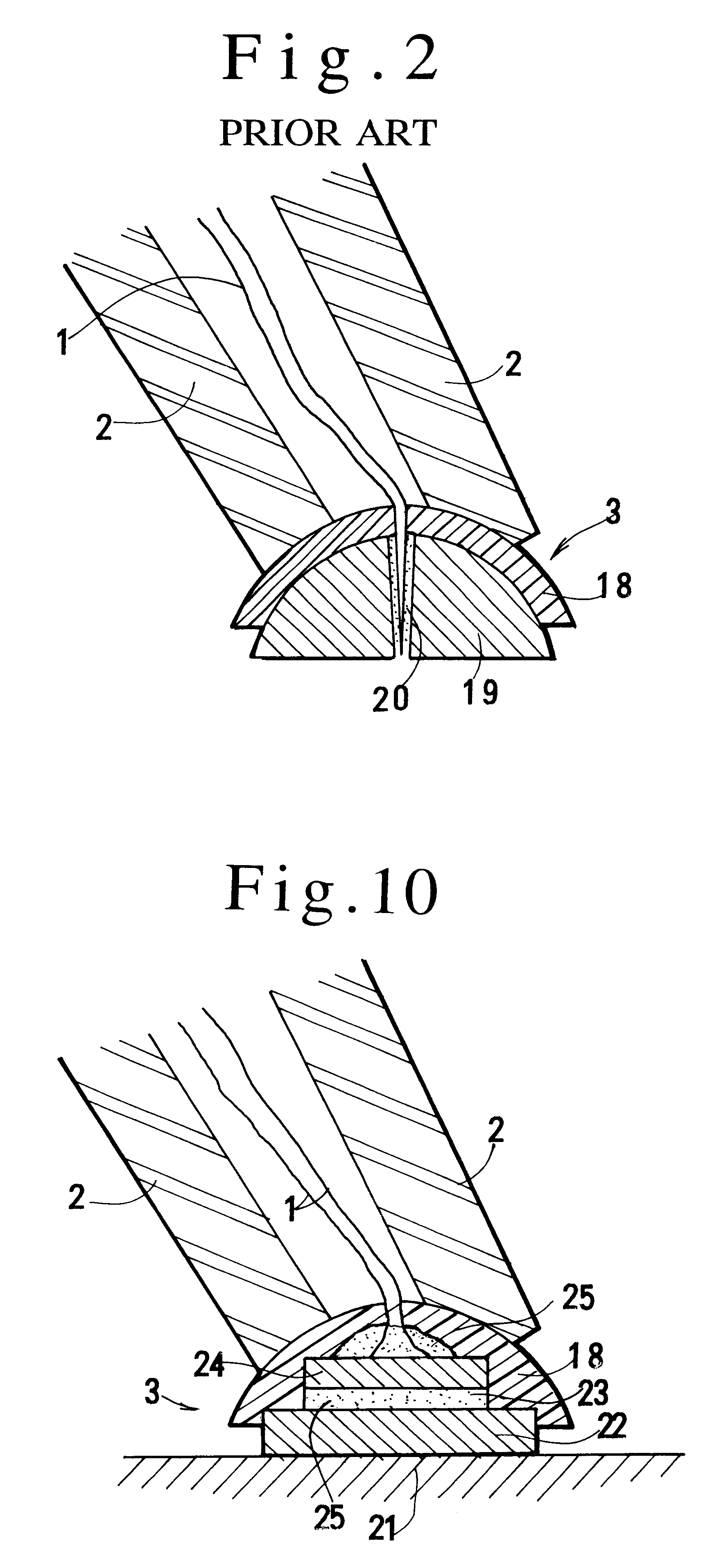
FIGS. 3 and 4 demonstrate Embodiment 1 coupling two independent discs for holding crossing tips of a thermocouple and a brazing material. The plates are independent, equivalent discs of copper. The three storied sensor head is also a disc. The diameter is, for example, about 0.8 mm. This embodiment is utilized for an asymmetric head having different discs as shown in FIG. 10. Since two independent round discs are employed, the embodiment has an advantage of the rotational symmetry. The bottom disc contacter ensures tight contact of the sensor to an object. The copper disc enhances the heat conduction for maintaining thermal equilibrium with the object.

embodiment 2 (a unified plate having symmetric discs ; fig.5 , fig.6)

[Embodiment 2 (A Unified Plate Having Symmetric Discs; FIG. 5, FIG. 6)]

A starting metal plate can be a unified plate having two disc parts. FIG. 5 and FIG. 6 denote Embodiment 2. A disc part 22 is coupled to another disc part 24 via a joint portion 28. A sensor head 3 is produced by putting crossing tips 26 of wires of a thermocouple 1 and a brazing material 25 on the disc part 22, bending the joint portion 28 for overlapping the disc 24 on the crossing tips 26 and sticking the plates together. The sensor head 3 is also made by putting the crossing tips 26 of wires of the thermocouple on the disc part 22, bending the joint portion 28 for overlapping the disc part 24 on the crossing tips 26, injecting the brazing material 25 into a gap between the disc parts for unifying the two disc parts. The production process of Embodiment 2 is easier than Embodiment 1. The joint portion 28 can either be left untouched or be eliminated by polishing.

embodiment 3 (a unified plate having asymmetric discs ; fig.7 , fig.8)

[Embodiment 3 (A Unified Plate Having Asymmetric Discs; FIG. 7, FIG. 8)]

Another starting plate has asymmetric discs as shown in FIG. 7 and FIG. 8. The plate is a copper plate having a central disc 22, joints 28 and 29, convex disc part 31 and concave disc part 30 which are connected to the central disc 22 via the joints 28 and 29. The joints 28 and 29 are half-thinned by etching. The concave disc part 30 has an aperture 32. A head 3 is assembled by positioning a crossing part 26 of a thermocouple 1, bending the joint 28, pressing the crossing part 26 by the concave disc part 30, bending the joint 29, pressing the crossing part 26 by the convex disc part 31, pulling out the wires of the thermocouple 1 from apertures 33 between two disc parts (FIG. 8), injecting a brazing material 25 into a thin space between the central disc part and the concave and convex disc parts for fixing the three disc parts together with the tips 26. Otherwise, supplying the brazing material to the disc 22 pr...


PUM

PropertyMeasurementUnit
diameteraaaaaaaaaa
diameteraaaaaaaaaa
thicknessaaaaaaaaaa

Abstract

A surface temperature sensor head including a first layer made of a material of a heat conductivity higher than 100 W / mK, a second layer having a crossing tips of a thermocouple and a brazing material and a third layer made of a material of a heat conductivity higher than 100 W / mK, the brazing material unifying the crossing tips, the first layer and the third layer. The sensor head enables a temperature prober to measure temperatures of an object non-destructively with high spatial resolution.

Description

BACKGROUND OF THE INVENTON1. Field of the InventionThis invention relates to an improvement of a surface temperature sensor head. A laser diode (LD) is one of the most important key devices of optical communication systems.This invention claims the priority of Japanese Patent Application No.11-344569 (344569 / 1999) filed Dec. 3, 1999 which is incorporated herein by reference.Since high density current flows in a tiny LD chip, the current produces large heat in the laser diode. The large heat raises the temperature of the LD chip. The high temperature deteriorates the properties and decreases the reliability of the LD. Further, the large heat changes the oscillation frequency of the LD or shortens the lifetime of the LD. Thermal analysis on the LDs has been energetically carried out for enhancing the property and the efficiency of LDs.The multiwavelength transmission technology attracts attention. Application of LDs to the light source of the multiwavelength transmission requires more...

Claims


Application Information

Patent Timeline
Patent Type & Authority Patents(United States)
IPC IPC(8): G01K1/14G01K7/04G01K7/02
CPCG01K1/143G01K7/04
Inventor TATOH, NOBUYOSHI
Owner SUMITOMO ELECTRIC IND LTD
Features
  • R&D
  • Intellectual Property
  • Life Sciences
  • Materials
  • Tech Scout
  • Unparalleled Data Quality
  • Higher Quality Content
  • 60% Fewer Hallucinations
Learn More