Method and device for applying pretensed tension-proof reinforcing strips to a construction

a technology of tension-proof reinforcing strips and prestressing, which is applied in the direction of building repairs, applications, manufacturing tools, etc., can solve the problems of potential weak spots, short lengths of lamellar steel strips, and relatively short strips that can be applied

Inactive Publication Date: 2002-10-15
EMPA EIDGENOESSISCHE MATERIALPRFUNGS & FORSCHUNGSANSTALT
View PDF4 Cites 28 Cited by
  • Summary
  • Abstract
  • Description
  • Claims
  • Application Information

AI Technical Summary

Problems solved by technology

Lamellar steel strips can only be supplied in short lengths, and hence only relatively short strips can be applied.
This means that where there are lengthy spans, joints between the lamellae are unavoidable, thereby inevitably leading to potential weak spots.
Furthermore, handling heavy lamellar steel strips on a building site is an awkward matter, and can cause considerable technical problems in the case of high-level constructions, or constructions which are otherwise difficult to access.
In addition, there exists a risk of the steel rusting on the underside of the strips, even if corrosion protection treatment is carefully accomplished, i.e. of corrosion on the contact surface between the steel and the concrete, which can result in the strip becoming detached, and thus a loss of the reinforcement.
This presupposes the availability of rigid anchorage points for attaching these straps, but these are not, however, always provided in practice, and are not disclosed in French Patent Reference 2,594,871.
Furthermore, the method disclosed in that document does not allow for the strip to be pressed against the structure at the same time as the bonding process, as is required to achieve reliable bonding.
One remaining difficult point is therefore the problem of anchoring the carbon fibre lamellae during the prestressing process, given that prestressing forces are of several tens of thousands of N. These enormous forces have to maintain the lamella to be applied under tension against the construction itself, at least until the adhesive has hardened completely.

Method used


Image

  • Method and device for applying pretensed tension-proof reinforcing strips to a construction
  • Method and device for applying pretensed tension-proof reinforcing strips to a construction
  • Method and device for applying pretensed tension-proof reinforcing strips to a construction

Examples


Embodiment Construction

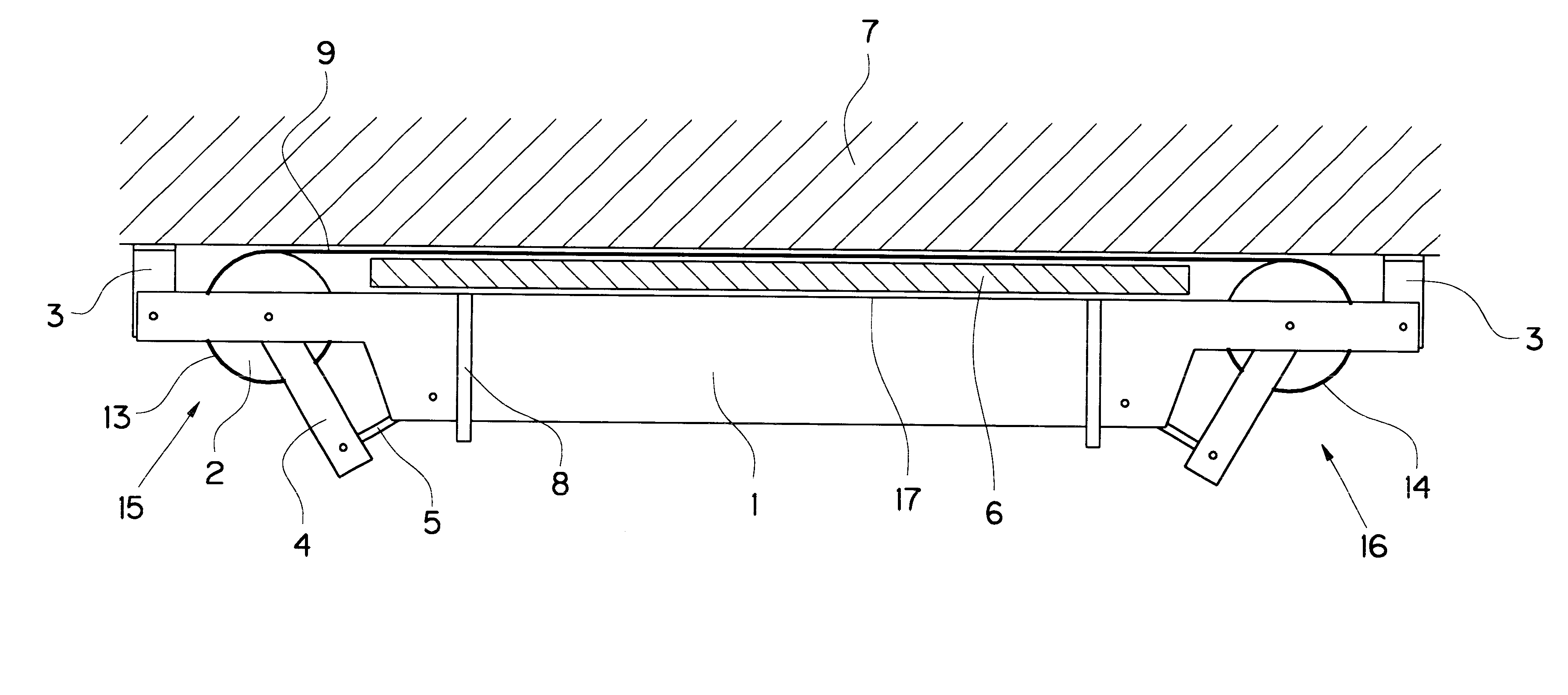
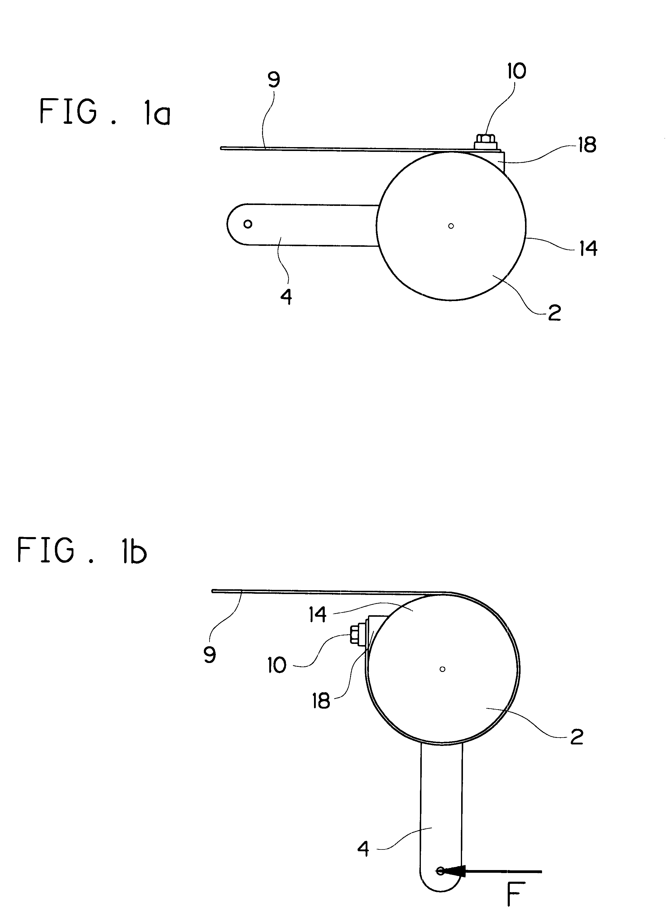
FIG. 1a shows one basic principle of the device or apparatus of this invention. The device comprises a curved, rotatable surface 14, which is formed here by the outer surface of wheel 2. One end of the reinforcing strip to be prestressed, namely the fibre reinforced plastic lamella 9, is attached to the surface 14. The other end of plastic lamella 9 can be tension-proofly anchored by some other means, or in exactly the same way as shown. In the example shown, a holding device 18 is provided on the curved surface 14, i.e. in this case to the outside of the wheel, to which strip 9 can be fixed with clamps and at least one screw 10. The plastic lamella 9 is a strip which can be a few centimeters wide and about one millimeter thick. The curved rotatable surface 14, i.e. the wheel 2 in this example, is connected to a lever 4 which can be pivoted around the axis of the wheel, clockwise in this drawing, to rotate the wheel 2 and the curved surface 14 with it.

FIG. 1b shows this part of the ...


PUM

PropertyMeasurementUnit
thicknessaaaaaaaaaa
thicknessaaaaaaaaaa
thickaaaaaaaaaa

Abstract

Lamellar, fibre-reinforced plastic strips can be used to reinforce a linearly expanded or flat construction part having a support function against any bending stress to which it is exposed. The strips are usually applied to the construction from the outside, or from the inside in the case of hollow structures, and fixed by an adhesive. The lamellar strips are pretensed with a tensioning device, treated with adhesive in a pretensed state, and then moved to the area to be treated together with the tension device. The tension device is provisionally fixed to the construction with displaceable fixing devices and pressed against said construction. Thereafter the lamellar strips are pressed against the construction by means of an air bag or air hose until the adhesive has hardened.

Description

1. Field of the InventionThis invention relates to a method and a device for applying prestressed, tension-proof reinforcing strips to constructions, the strips being fixed to the construction with an adhesive.2. Description of Related ArtFor many years, both research and practical work have been done to find a way of strengthening steel concrete constructions after completion by applying an additional reinforcement. The beginnings of this technology are described in a report by J. Bresson entitled "Nouvelles recherches et applications con.cedilla.emant l'utilisation des collages dans les structures Beton plaque", Annales ITBTP No. 278 (1971), Serie beton, Beton arme No. 116. The technique dates back to the 1960s. Bresson concentrated on research into the bonding stresses in the vicinity of the anchorages of lamellar steel strips bonded to constructions with adhesive. One advantage is that over the last 25 years, engineers have been able to reinforce existing steel constructions suc...

Claims


Application Information

Patent Timeline
Patent Type & Authority Patents(United States)
IPC IPC(8): E04G23/02E04C5/08E04C5/07E04C5/00
CPCE04C5/07E04C5/08E04G23/0218E04G2023/0251E04G2023/0259
Inventor MEIER, URSSTOCKLIN, IWANWINISTORFER, ANDREAS
Owner EMPA EIDGENOESSISCHE MATERIALPRFUNGS & FORSCHUNGSANSTALT
Why Eureka
Try Eureka