Multi-band filter system for wireless communication receiver

a filter system and wireless communication technology, applied in the field of mobile wireless communications receivers, can solve the problems of excessive loading of receiver components, no one of these three standards has yet achieved universal worldwide coverage, and the excessive space consumed by receiver components for the three different bands

Inactive Publication Date: 2002-10-15
SKYWORKS SOLUTIONS INC
View PDF8 Cites 77 Cited by
  • Summary
  • Abstract
  • Description
  • Claims
  • Application Information

AI Technical Summary

Problems solved by technology

Moreover, no one of these three standards has yet achieved universal worldwide coverage.
However, unique problems exist which have heretofore prevented extension of this development to a handset capable of handling three or more bands.
One such problem is the excessive loading caused on the receiver components for a selected band by the receiver components for the other two bands.
Another problem is the excessive space consumed by the receiver components for the three different bands.
This latter problem is particularly acute given the demands of users for compact and easily portable handsets.

Method used


Image

  • Multi-band filter system for wireless communication receiver
  • Multi-band filter system for wireless communication receiver
  • Multi-band filter system for wireless communication receiver

Examples


first embodiment

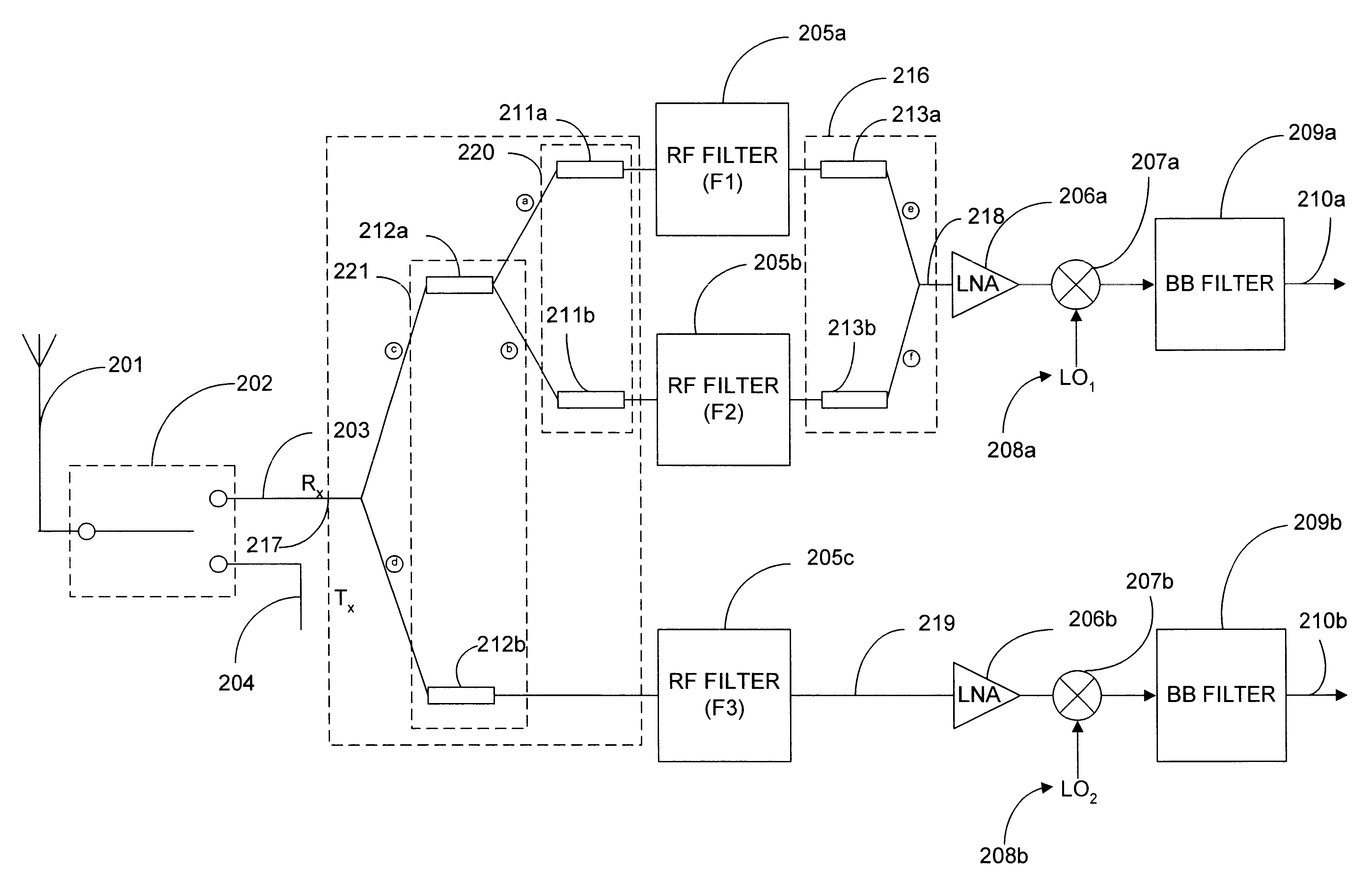
a method of implementing the system of FIG. 3 is illustrated in FIGS. 4A-4C, in conjunction with FIGS. 8A-8B. In a first step, illustrated in FIG. 4A, the input impedance of filter 205a is measured at the center frequency f.sub.2 of filter 205b. This value is referred to as Z.sub.in (f.sub.2). Then, the length of line 211a, L.sub.1, is determined so that the input impedance of filter 205a as adjusted by line 211a at the center frequency of filter 205b, Z.sub.in (f.sub.2)*, appears infinite. This step is illustrated in FIGS. 8A-8B, which illustrate a representation of Smith chart 600, normalized with the characteristic impedance of the material used for line 211a. The perimeter of the Smith chart is identified with numeral 602, the unit circle on the Smith chart is referred to with numeral 604, and the horizontal axis on the Smith chart is referred to with numeral 601. With reference to FIG. 8A, the impedance of the filter 205a, at the center frequency of its passband, f.sub.1, is id...

second embodiment

a method of implementing a filter system of the subject invention is illustrated in FIG. 5A. This figure represents a procedure which is employed for one or more ports, whether input or output, of a filter within a filter system of the subject invention. In step 400, the phase of the reflection coefficient .GAMMA. (or the parameter S.sub.11) at the port of the filter is measured. In step 401, the required length of a transmission line to be coupled to that port is determined based on the phase change which is required to achieve the electrical appearance of infinite appearance at an opposing frequency, that is, a frequency representative of or characteristic of the passbands of one or more other filters within the filter system of the subject invention. Then, in step 402, a transmission line of the length determined in step 401 is coupled to the port of the filter.

third embodiment

FIG. 5B illustrates a method of implementing a filter system of the subject invention. Again, this method is preferably utilized for one or more ports of at least one filter of the filter system of the subject invention. In step 500, the frequency of a network analyzer is set to an opposing frequency, that is, a frequency representative of or characteristic of the passbands of one or more other filters within the filter system is determined. In step 501, the phase of the network analyzer is calibrated or "zeroed" while disconnected from the filter in question. In step 502, the network analyzer is used to determine the phase of the reflection coefficient at the port of the filter. In step 503, the phase change required to achieve the electrical appearance of infinite impedance at the port of the filter is determined, and the required length of a transmission line in terms of wavelength is determined from that phase change. In step 504, the length from step 503 is translated into a ph...


PUM


Abstract

A filter system comprising three or more filters, each having different passbands, and an impedance adjusting network coupled between a filter system ports and each of the ports of at least two of the filters to adjust the port impedances of the filters coupled to the network. The adjusted port impedance of each filter at a frequency representative of at least one of the other filters coupled to the network is at a non-loading level. In one embodiment, the filter system is configured for use in a wireless communication receiver and / or handset.

Description

I. Field of the InventionThis invention relates generally to the field of mobile wireless communications receivers, and more particularly, to a wireless communications receiver capable of operation in multiple frequency bands.II. Background of the InventionIn recent years, multiple wireless communications standards have been deployed governing the wireless interface between base stations and the mobile handsets serviced by the base stations. A geographical area is divided into a plurality of cells, each corresponding to a base station, and with the mobile handsets in a cell serviced by the base station corresponding to the cell. The base stations in turn are linked to a base station controller which in turn are linked to the Public Switched Telephone Network (PSTN) through one or more E1 / T1 lines.The GSM (Global System for Mobile Communications) is a standard based on TDMA (Time Division Multiple Access) technology that governs wireless communications over much of Europe. The DCS (D...

Claims


Application Information

Patent Timeline
Patent Type & Authority Patents(United States)
IPC IPC(8): H04B1/40
CPCH04B1/005H04B1/006H04B1/406
Inventor AGAHI-KESHEH, DARIOUSHSNIDER, JAMES R.
Owner SKYWORKS SOLUTIONS INC
Why Eureka
Try Eureka