Oral cavity washer with video scope

a technology of video scope and oral cavity, which is applied in the field of video scope, can solve the problems of difficult to actually confirm on an image, and in ordinary households it is difficult to newly secure space to install a display

Inactive Publication Date: 2002-10-22
PANASONIC CORP
View PDF12 Cites 50 Cited by
  • Summary
  • Abstract
  • Description
  • Claims
  • Application Information

AI Technical Summary

Benefits of technology

A place where a liquid jetted for washing collides with an object, that is, teeth or gums, is located within the image pick-up range of the video scope, so that a washing operation can be performed while confirming a place to be washed on an image. In this manner, a place where this liquid is jetted is confirmed on the image while jetting liquid, whereby not only washing, but also a massage effect the gums and the like by pressure of water, can also be expected. Therefore the practical utility is improved.
An additional aspect of the present invention is the oral cavity washer with a video scope, wherein a jetting velocity of the fluid to said optical window is controlled so as to be lower than a jetting velocity of the fluid to said object.
A still yet additional aspect of the present invention is the oral cavity washer with a video scope according to, wherein said optical window is subjected to a water-repellent treatment, which secures transmission of visible light.
A still supplementary aspect of the present invention is the oral cavity washer with a video scope according to wherein said optical window is subjected to a hydrophilic treatment, which secures transmission of visible light.

Problems solved by technology

In this case, it is difficult to actually confirm on an image that a place which an operator observed with the video scope, and a place, to which water was jetted, coincide with each other.
Also, since oral cavity washing is usually performed within a limited space such as a lavatory, it is often difficult in ordinary households to newly secure space to install a display for displaying a video scope image.

Method used


Image

  • Oral cavity washer with video scope
  • Oral cavity washer with video scope
  • Oral cavity washer with video scope

Examples


first embodiment

(First Embodiment)

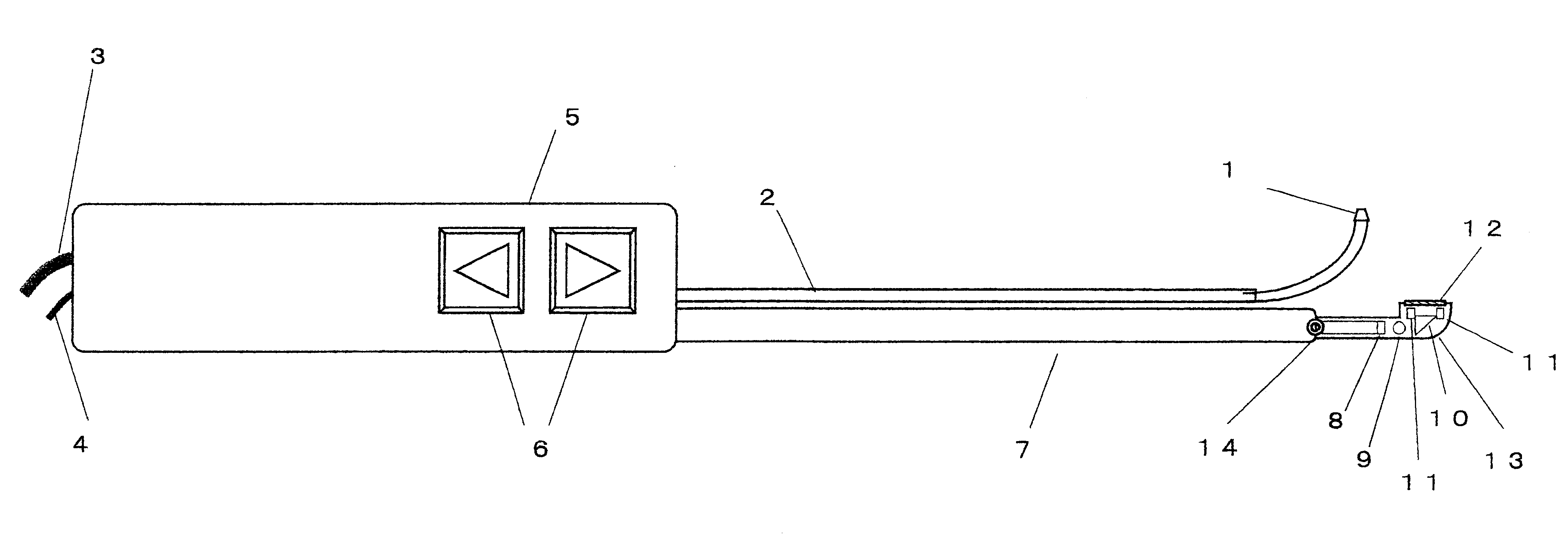
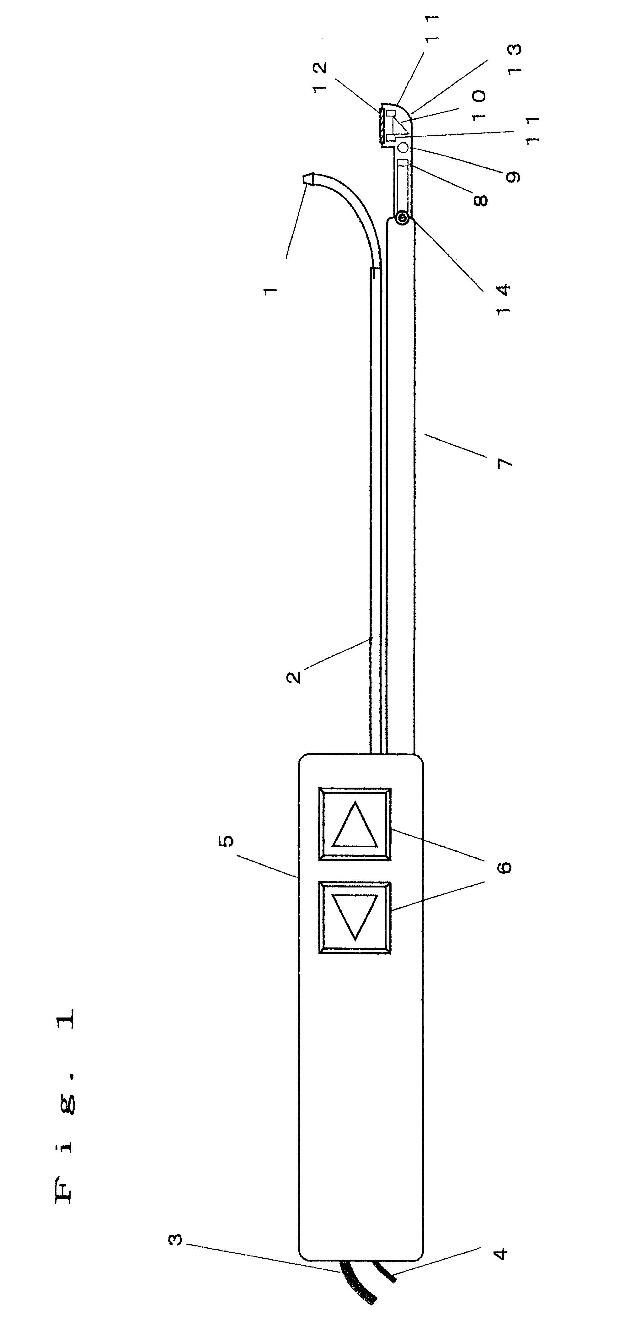
Hereinafter, with reference to FIGS. 1 to 3, the description will be made of an embodiment of the present invention.

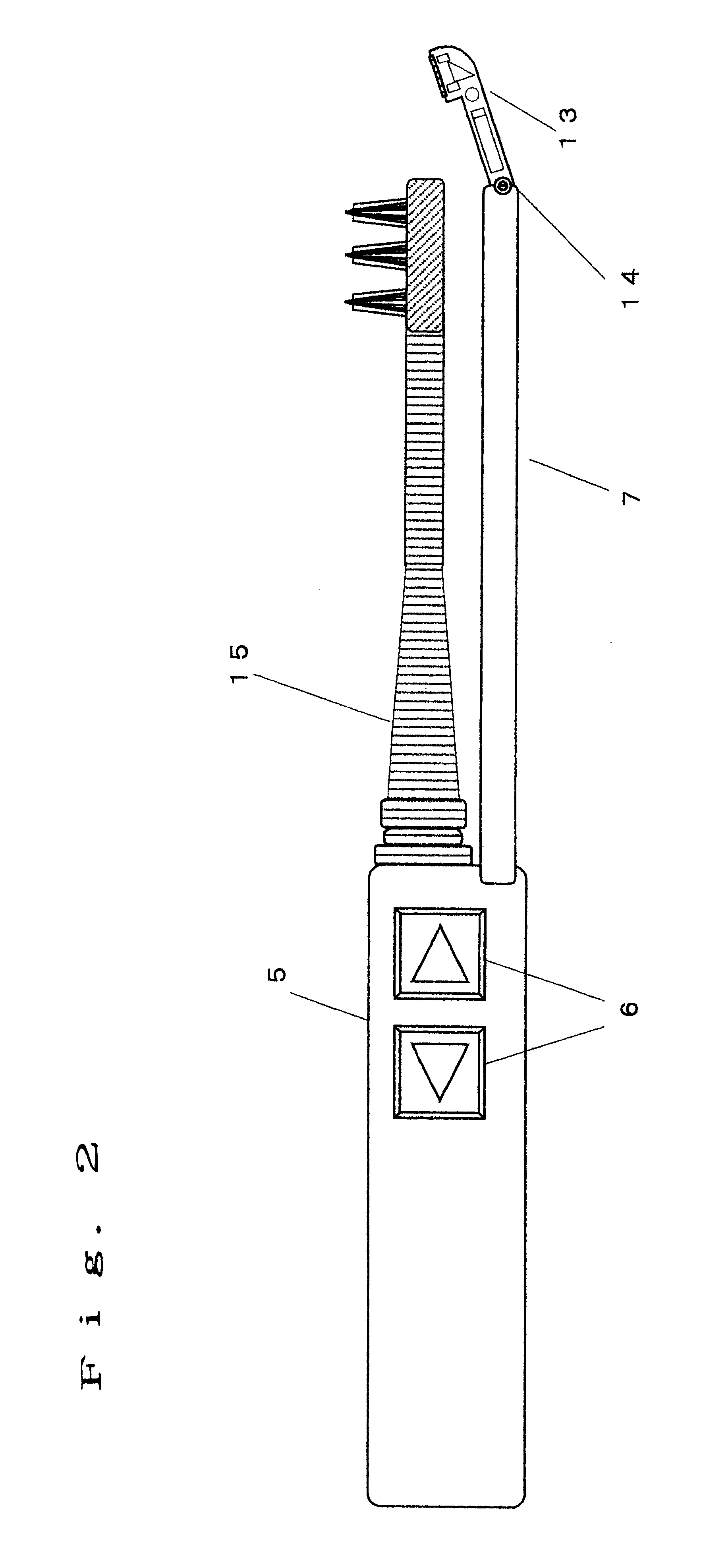
In the present embodiment, the nozzle for jetting liquid to an object can be replaced with a toothbrush. These are replaced as required, whereby it becomes possible not only to perform washing for jetting liquid, but also to clean teeth by a toothbrush. By having this replacement function, the video scope can be utilized not only on jetting liquid, but also on cleaning teeth, which is effective.

FIG. 1 is a side view showing a portion of an oral cavity washer with a video scope according to the present embodiment. In FIG. 1, reference numeral 1 denotes a nozzle for jetting liquid, and reference numeral 2 denotes a pipe for supplying liquid to be jetted to the nozzle 1 and fixing the nozzle 1 to a grip portion 5. Reference numeral 3 denotes a tube for supplying liquid to the nozzle 1 from the main body 16 shown in FIG. 3 through the grip portion 5 and t...

second embodiment

(Second Embodiment)

FIG. 4 is a side view showing a portion of an oral cavity washer with a video scope according to a second embodiment of the present invention except for the display (display 17). In FIG. 4, reference numerals 1 to 14 denote the same objects as those denoted by reference numerals 1 to 14 of FIG. 1, and have the same functions. Reference numeral 20 denotes a nozzle, which jets liquid such as water to the optical window 12. This liquid is sent from the main body 16 to the grip portion 5 through the tube 3, and is sent from the grip portion 5 to the nozzle 20 through the pipe housed in the video scope base 7. Jetting of liquid for washing this optical window 12 is controlled by a switch 6 provided at the grip portion 5 as described below.

During the washing operation for the object using liquid from the nozzle 1, bubbles or water droplets are prone to occur, and these bubbles or water droplets may adhere to the optical window 12 to hinder the image pick-up. At this tim...

third embodiment

(Third Embodiment)

With reference to FIG. 4, the description will be made of a third embodiment according to the present invention.

In the second embodiment, when bubbles or water droplets adhere to the optical window 12 to hinder the image pick-up during the washing operation, the switch 6 has been operated to jet the liquid to the optical window 12 from the nozzle 20 for removing the adhered bubbles or water droplets. At this time, when the jetting velocity of the liquid from the nozzle 1 to the washing object is high among others, bubbles or water droplets may adhere to the optical window 12 in a moment by rebounding even after removal due to jetting of the liquid from the nozzle 20 to hinder the image pick-up.

In order to cope with such a case, according to the present embodiment, the nozzle 1 and the nozzle 20 automatically jet the liquid alternately. The liquid sent by a pump installed in the main body 16 is controlled by a change-over valve installed within the grip portion 5, w...


PUM


Abstract

An oral cavity washer with a video scope, hasa video scope having image-forming means of forming an image from light from an object, an image pick-up device for converting the light from which the image is formed by the image-forming means into an electric signal, and a first grip portion for being held by an operator;a display for displaying an image picked up by the video scope; andan oral cavity washer having a nozzle for jetting a fluid and a second grip portion for being held by the operator, for washing an oral cavity by jetting the fluid to teeth or gums,wherein the first grip portion and the second grip portion are capable of being made integral with each other.

Description

1. Field of the InventionThe present invention relates to a video scope incorporating an image pick-up device such as a CCD for picking up an image of an interior of an oral cavity, and an oral cavity washer for washing the interior of the oral cavity by jetting fluid such as water onto teeth or gums.2. Related Art of the InventionIn recent years, a video scope using a CCD capable of picking up an image of a limited part while illuminating has been used for medical examination for a diseased part within the oral cavity in density, oral surgery and the like, and further for an operator to observe conditions of his own teeth or gums. In addition, in homes, there have become popular oral cavity washers for jetting water onto the teeth or gums with the aim of washing the interior of the oral cavity.For a video scope for performing such local image pick-up and a nozzle portion for jetting liquid of the oral cavity washer, there is required one easy to handle, capable of being operated by...

Claims


Application Information

Patent Timeline
Patent Type & Authority Patents(United States)
IPC IPC(8): A61B1/24A61C17/02A61C17/024G02B23/24H04N7/18
CPCA61B1/24A61B2560/0456A61C17/0202A61C17/024
Inventor KAWAMURA, TATUROU
Owner PANASONIC CORP
Why Eureka
Try Eureka