Intensity compensation for interchangeable chromatic point sensor components

a technology of intensity compensation and chromatic point sensor, which is applied in the field of precision measurement instruments, can solve the problems that the method disclosed in the '799 patent does not adequately address, and achieve the effect of more robust and stabl

Active Publication Date: 2010-11-11
MITUTOYO CORP
View PDF19 Cites 22 Cited by
  • Summary
  • Abstract
  • Description
  • Claims
  • Application Information

AI Technical Summary

Benefits of technology

[0017]As explained in greater detail below, application of the various error compensation factors outlined may effectively “smooth” the wavelength detector response as well the overall measurement distance calibration curve for a CPS. In add

Problems solved by technology

Deficiencies arise in the method of the '799 Patent because it is based on an idealization of chromatic point sensor (CPS) operation that is not achieved in practice.
For example, in particular, the method disclosed

Method used


Image

  • Intensity compensation for interchangeable chromatic point sensor components
  • Intensity compensation for interchangeable chromatic point sensor components
  • Intensity compensation for interchangeable chromatic point sensor components

Examples


second embodiment

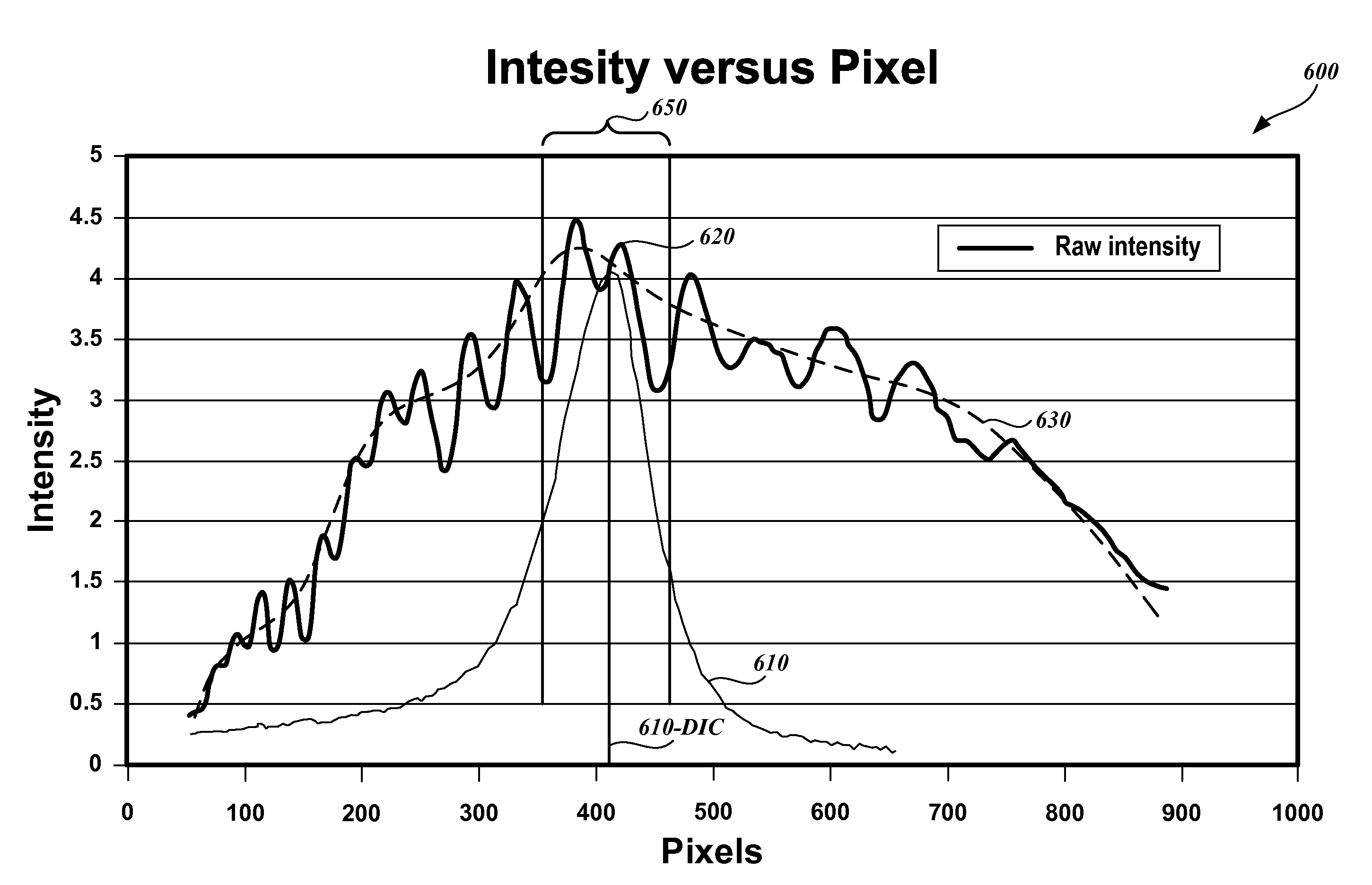
[0087]FIG. 9 illustrates a method for performing short-range error compensation in order to provide a set of short-range compensated measurement profile signals MSPSRCOMP(Z) and / or implement EQUATIONS 6-9 in manner analogous to that previously outlined with reference to FIG. 8B. In particular, FIG. 9 includes a diagram of a graph 900 illustrating the raw intensity profile signal data 620 shown in FIG. 6, which may be acquired as previously described with reference to FIG. 5. FIG. 9 also shows a short-range compensated signal 630′, short range variation data 925, and short range error compensation factors 950, determined as described below.

[0088]In the particular embodiment shown in FIG. 9, the short-range compensated signal 630′ is determined by applying mathematical operations to the raw intensity profile signal data 620, approximately as follows. An Equi-Ripple High Pass VI filter available in the commercial computer program LabView® is applied to the raw intensity profile signal ...

first embodiment

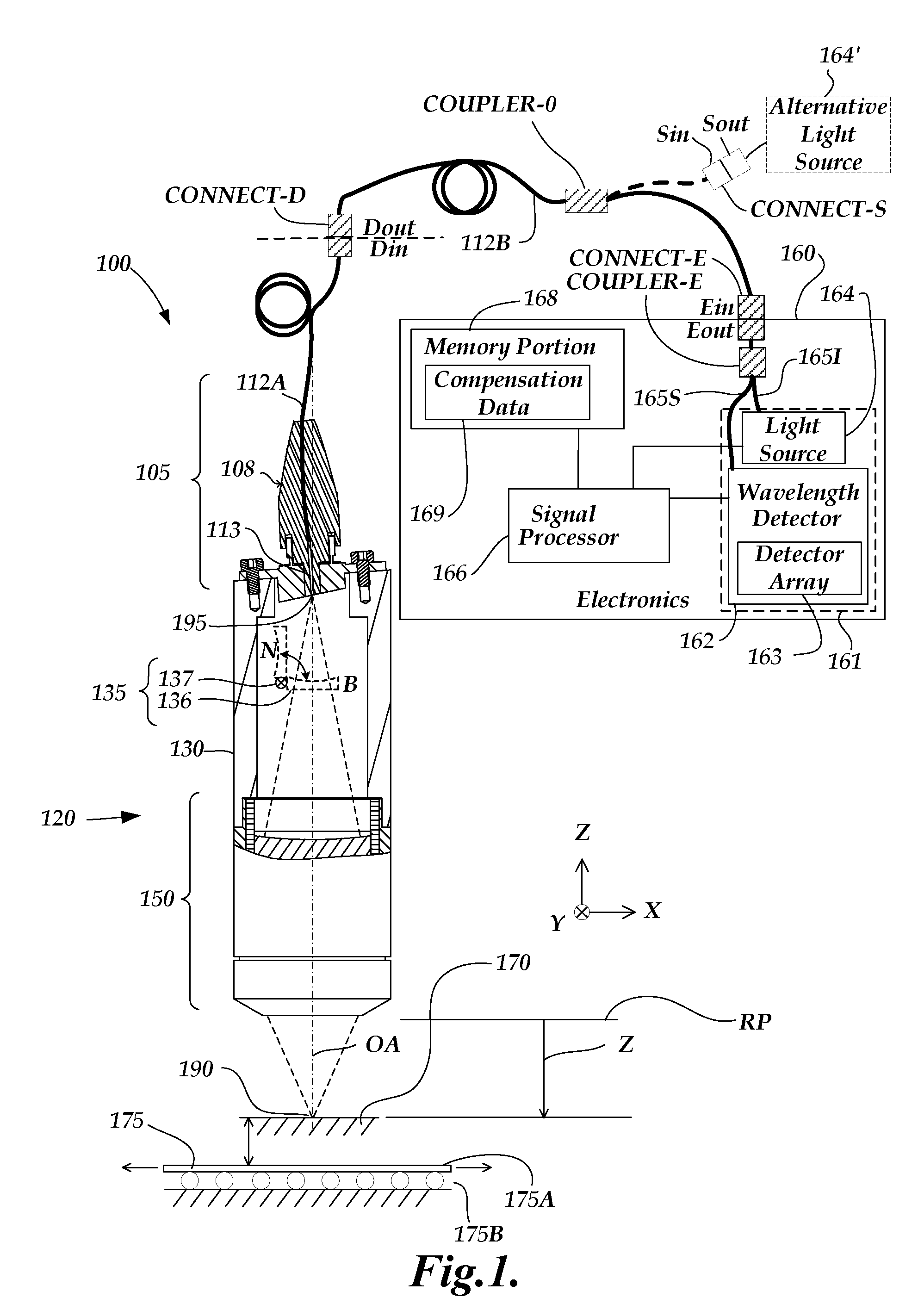
[0091]FIG. 11 is a flow diagram illustrating an exemplary routine 1100 for an error compensation factor determination method of the present invention. In some embodiments, methods for error compensation factor determination according to this invention may be implemented by operations of the CPS electronics (e.g., by execution of routines residing in memory portion 168, as implemented under control of the signal processor 166.) The CPS electronics may include a means for activating an error compensation factor determination mode, in contrast to the normal measuring operation mode of the CPS, if desired. In other embodiments, methods for error compensation factor determination according to this invention may be implemented by operations a host system (e.g., a general purpose personal computer) connected to and interacting with the CPS electronics. As shown in FIG. 11, at a block 1101, a CPS electronics including a CPS source+detector subsystem comprising a CPS light source and a CPS w...


PUM


Abstract

Methods for providing compensation for non-uniform response of a light source and wavelength detector subsystem of a chromatic point sensor (CPS) are provided. Light from the light source is input into an optical path that bypasses the measurement path through a CPS optical pen and provides the bypass light to the wavelength detector to provide a raw intensity profile distributed over the pixels of detector. The resulting set of raw intensity profile signals are analyzed to determine a set of error compensation factors for wavelength-dependent intensity variations that occur in the raw intensity profile signals. Later, the error compensation factors may be applied to reduce distortions and asymmetries that may otherwise occur in the shape of the signals in the peak region of CPS distance measurement profile signal data. The disclosed methods may provide enhanced accuracy, robustness, field-testing, and interchangeability for CPS components, in various embodiments.

Description

FIELD OF THE INVENTION[0001]The invention relates generally to precision measurement instruments, and more particularly to chromatic point sensors and similar optical distance determining devices.BACKGROUND OF THE INVENTION[0002]It is known to use chromatic confocal techniques in optical height or distance sensors. As described in U.S. Patent Application Publication No. US2006 / 0109483 A1, which is hereby incorporated herein by reference in its entirety, an optical element having axial chromatic aberration, also referred to as axial or longitudinal chromatic dispersion, may be used to focus a broadband light source such that the axial distance to the focus varies with the wavelength. Thus, only one wavelength will be precisely focused on a surface, and the surface height or distance relative to the focusing element determines which wavelength is best focused. Upon reflection from the surface, the light is refocused onto a small detector aperture, such as a pinhole or the end of an op...

Claims


Application Information

Patent Timeline
IPC IPC(8): G01B11/24
CPCG01B11/0608G02B21/0064G01B2210/50G01B21/045
Inventor SESKO, DAVID WILLIAM
Owner MITUTOYO CORP
Why Eureka
Try Eureka