Efficient in-rush current limiting circuit with dual gated bidirectional hemts

a technology of inrush current limiting circuit and gated bidirectional hemt, which is applied in the direction of electric variable regulation, process and machine control, instruments, etc., can solve the problems of high reverse recovery loss, control of inrush current at startup, and limit the maximum switching frequency, so as to achieve economic and convenient implementation, improve the effect of conventional practice and functional improvemen

Inactive Publication Date: 2008-04-08
INFINEON TECH AMERICAS CORP
View PDF4 Cites 18 Cited by
  • Summary
  • Abstract
  • Description
  • Claims
  • Application Information

AI Technical Summary

Benefits of technology

[0015]Circuits according to the various aspects of the invention require minimal addition of extra components, making the device economical and easily implemented as an IC with the rest of boost converter. Functional improvements over conventional practice are also obtained. For the synchronous rectification function, only the small forward voltage of the low voltage Schottky diode (0.2-0.3V) and the RDSon loss of the switch contribute to conduction losses, making the circuit very efficient. This represents an advantage even compared to the most advanced wide bandgap rectifier diodes (SiC and GaAs) which exhibit high conduction losses. Also, there are no reverse recovery losses, but only capacitive discharge of the switch capacitance.
[0016]For the inrush current limiting function, an important advantage is that the current path can be opened at any given time, providing a solid state fuse function. A complete and accurate inrush current control is therefore possible.

Problems solved by technology

There are typically two problems that arise in boost topology configurations, namely high reverse recovery losses, and control of inrush current at startup.
As to the first problem, when MOSFET 16 turns on during normal operation, the reverse recovery charge of boost diode 20 causes significant switching losses, seriously limiting the maximum switching frequency.
The second problem typically occurs at system startup, when the output capacitor 22 is discharged: the output capacitor is charged by the rectified AC line.
The amplitude of the charging current is limited by the impedance of the input loop, resulting in a significant inrush current that can cause component failures.
In all of these, however, the solutions address only one of the two main issues (inrush and reverse recovery losses) and they all use additional components which can not conveniently be fabricated as part of the converter IC.

Method used


Image

  • Efficient in-rush current limiting circuit with dual gated bidirectional hemts
  • Efficient in-rush current limiting circuit with dual gated bidirectional hemts
  • Efficient in-rush current limiting circuit with dual gated bidirectional hemts

Examples


Embodiment Construction

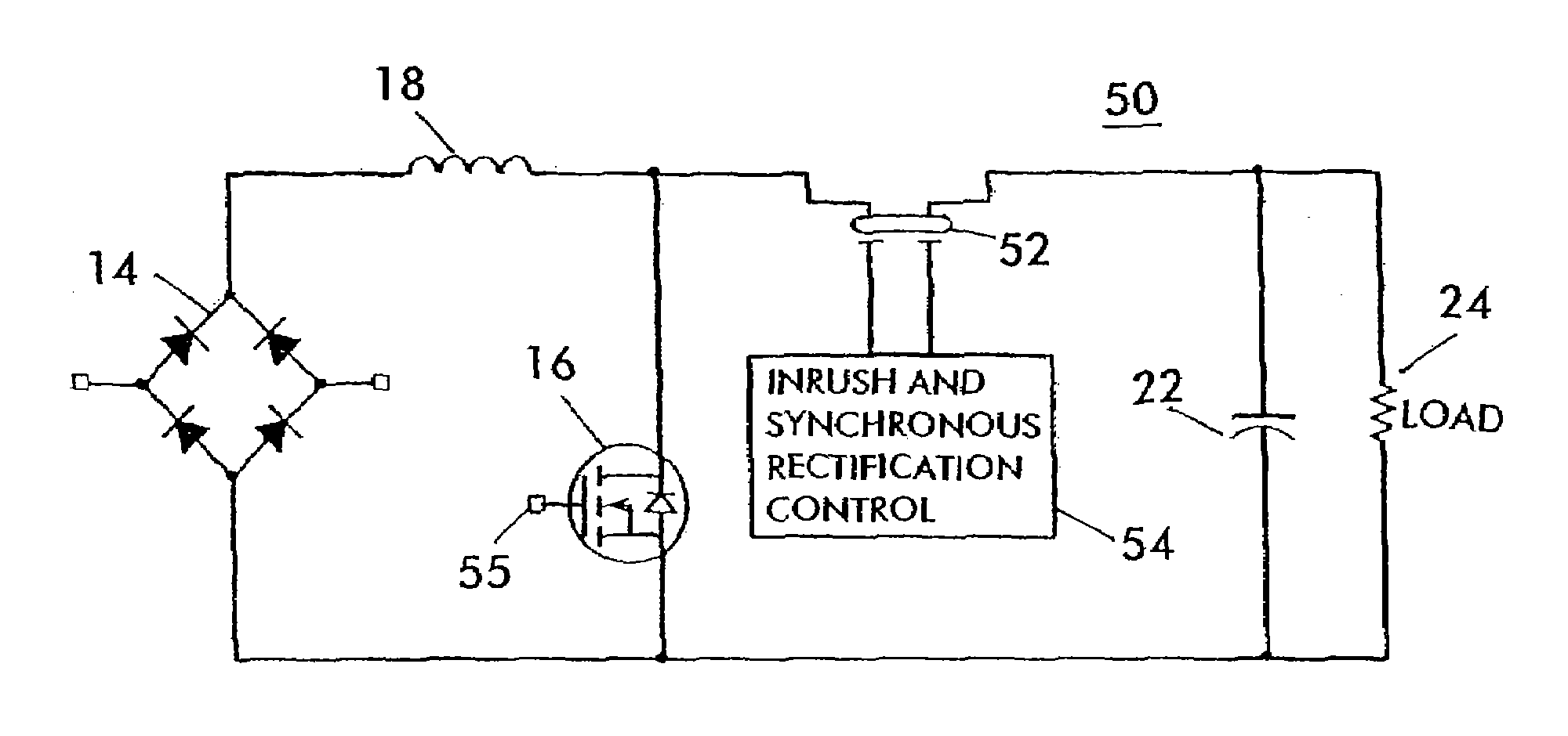
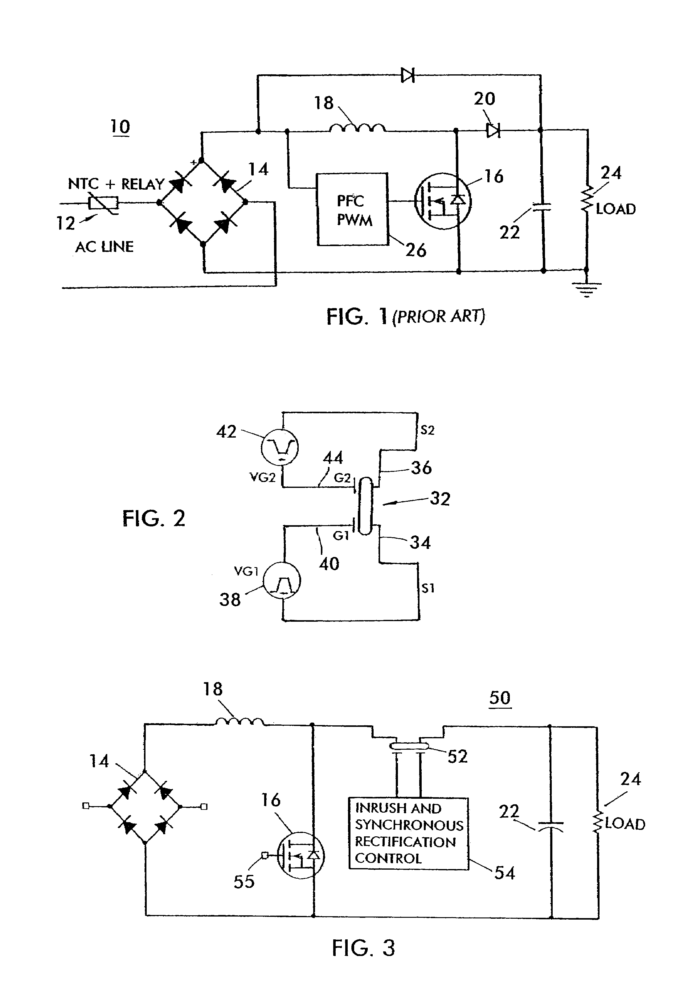
[0029]Referring now to FIG. 3, the basic concept of a synchronous boost converter, generally designated at 50, has the same general architecture as the conventional circuit of FIG. 1 with a diode rectifier bridge 14, a low side MOSFET 16, a boost choke 18 and an output capacitor 22, to which a load circuit 24 is connected in parallel. The boost diode of FIG. 1, however, is replaced by a bidirectional normally on switch 52 of the type described above, and illustrated in FIG. 2. Inrush and synchronous rectification control is provided by a logic unit 54, which may be of any suitable or desired type, or as described in the exemplary embodiments described below, generates the appropriate control signals for switch 52. MOSFET 16 is driven in conventional fashion by suitable pulse width modulation logic (not shown).

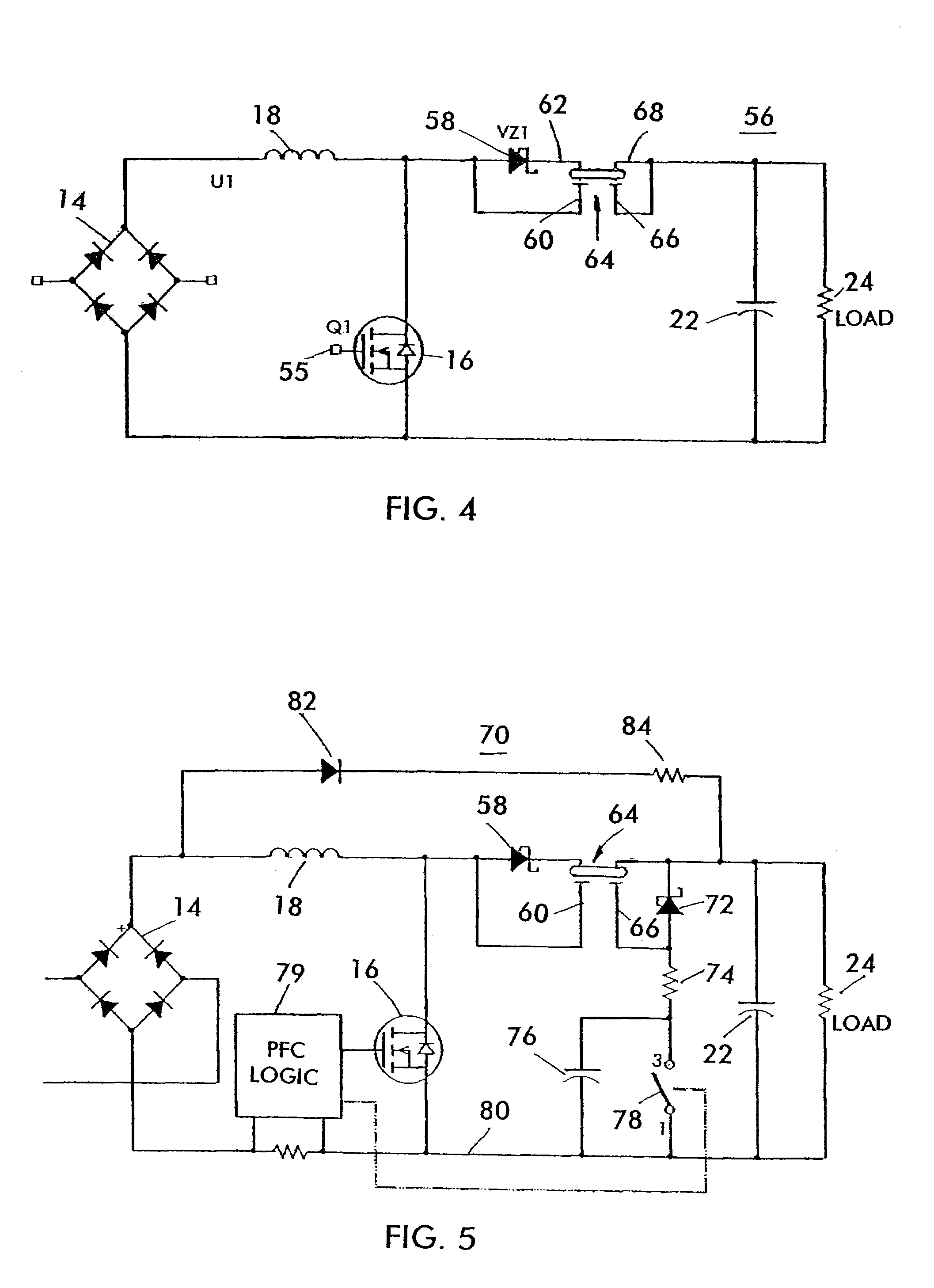
[0030]A preferred exemplary, but non-limiting implementation employs a Schottky diode 58 connected between the line side gate and source terminals 60 and 62 of bidirectional sw...


PUM


Abstract

A boost converter in accordance with an embodiment of the present application includes an input rectifying bridge adapted to rectify an input AC voltage, a first inductor connected to the input rectifying bridge, a output capacitor coupled to first inductor for connection to a DC bus, a first bidirectional semiconductor switch coupled between the output capacitor and the first inductor, a second inductor positioned adjacent to the first inductor with a first end connected to a common ground and a second bidirectional semiconductor switch positioned between the second inductor and the output capacitor. An inrush control device may be provided to control the first and second bidirectional semiconductor switches to prevent current inrush.

Description

REFERENCE TO RELATED APPLICATIONS[0001]The present application is a continuation-in-part of U.S. patent application Ser. No. 11 / 202,134 entitled SELF-DRIVEN SYNCHRONOUS RECTIFIED BOOST CONVERTER WITH INRUSH CURRENT PROTECTION USING BIDIRECTIONAL NORMALLY ON DEVICE filed Aug. 11, 2005 now U.S. Pat. No. 7,276,883, which claimed benefit to and priority from U.S. Provisional Application 60 / 600,914 filed Aug. 12, 2004, the entire contents of each of which are hereby incorporate by reference herein.[0002]The present application also claims benefit to and priority from U.S. Provisional Patent Application No 60 / 694,329 entitled EFFICIENT IN-RUSH CURRENT LIMITING CIRCUIT WITH DUAL GATED BIDIRECTIONAL HEMTs: REGULAR BOOST AND FLYBACK STRUCTURES INTEGRATION THROUGH CONTROLLED CASCODED RECTIFIER filed Jun. 27, 2005, the entire contents of which are hereby incorporated by reference herein.BACKGROUND OF THE INVENTIONRelevant Art[0003]Power factor correction (PFC) is required by international stan...

Claims


Application Information

Patent Timeline
Patent Type & Authority Patents(United States)
IPC IPC(8): G05F1/613G05F3/16
CPCH02M1/36H02M1/4225H02M3/1588H01L27/0251Y02B70/126Y02B70/1466Y10S323/908Y02B70/10
Inventor SALATO, MAURIZIOSOLDANO, MARCO
Owner INFINEON TECH AMERICAS CORP
Why Eureka
Try Eureka