Eyeglass frame and lens tracing apparatus and method

a technology of tracing apparatus and lens, which is applied in the direction of circular curve drawing instruments, instruments, spectales/goggles, etc., can solve the problems of tracer tracing reading errors

Inactive Publication Date: 2002-11-05
6338631 CANADA
View PDF12 Cites 30 Cited by
  • Summary
  • Abstract
  • Description
  • Claims
  • Application Information

AI Technical Summary

Problems solved by technology

It is preferable that the tracer apparatus not deflect or deform the frames during tracing, which can result in errors in the tracing readings produced by the tracer.
Moreover, the tracer apparatus should not bind on or come free of the edge which is being traced as these conditions result in errors in the tracing readings produced by the tracer.

Method used


Image

  • Eyeglass frame and lens tracing apparatus and method
  • Eyeglass frame and lens tracing apparatus and method
  • Eyeglass frame and lens tracing apparatus and method

Examples


Embodiment Construction

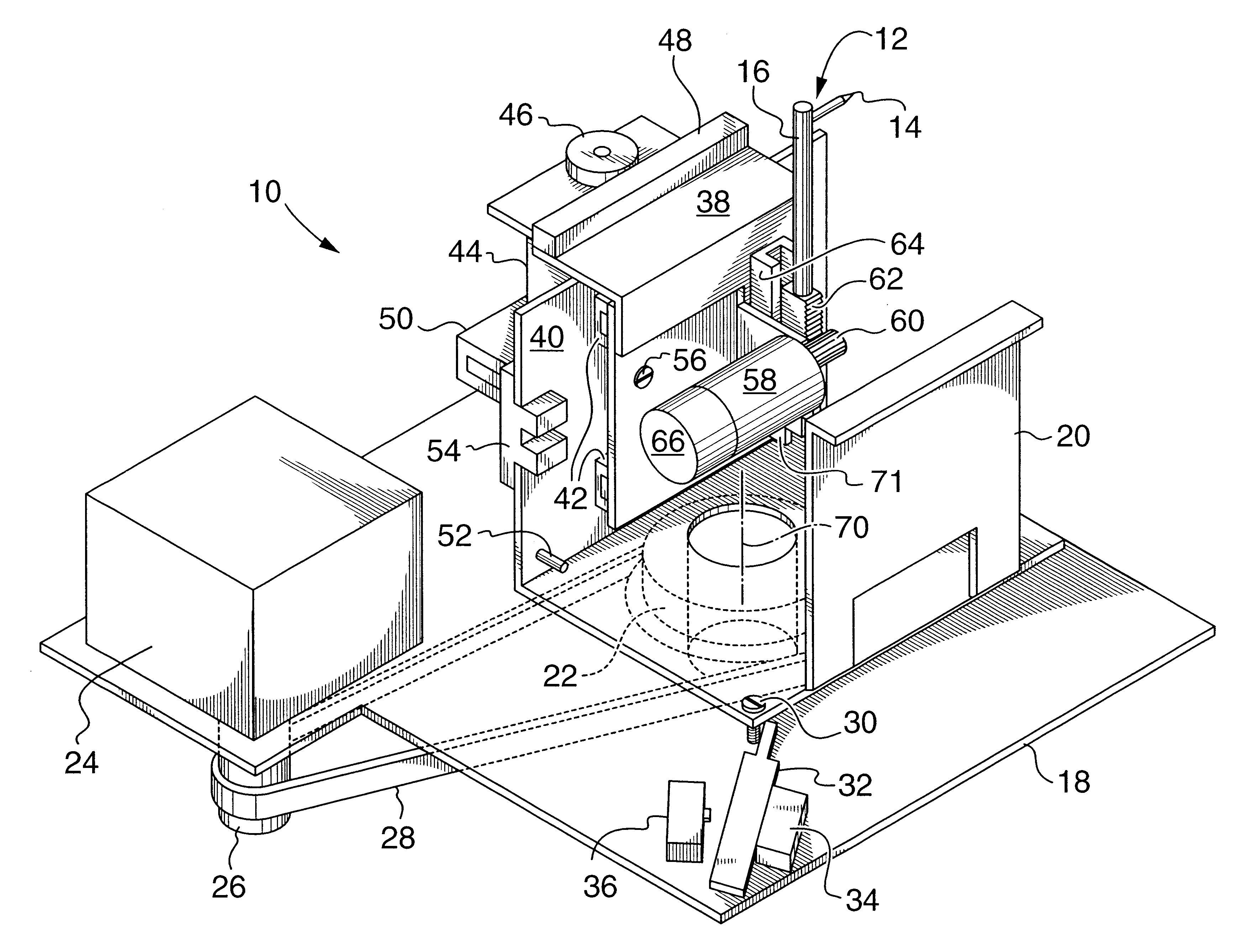
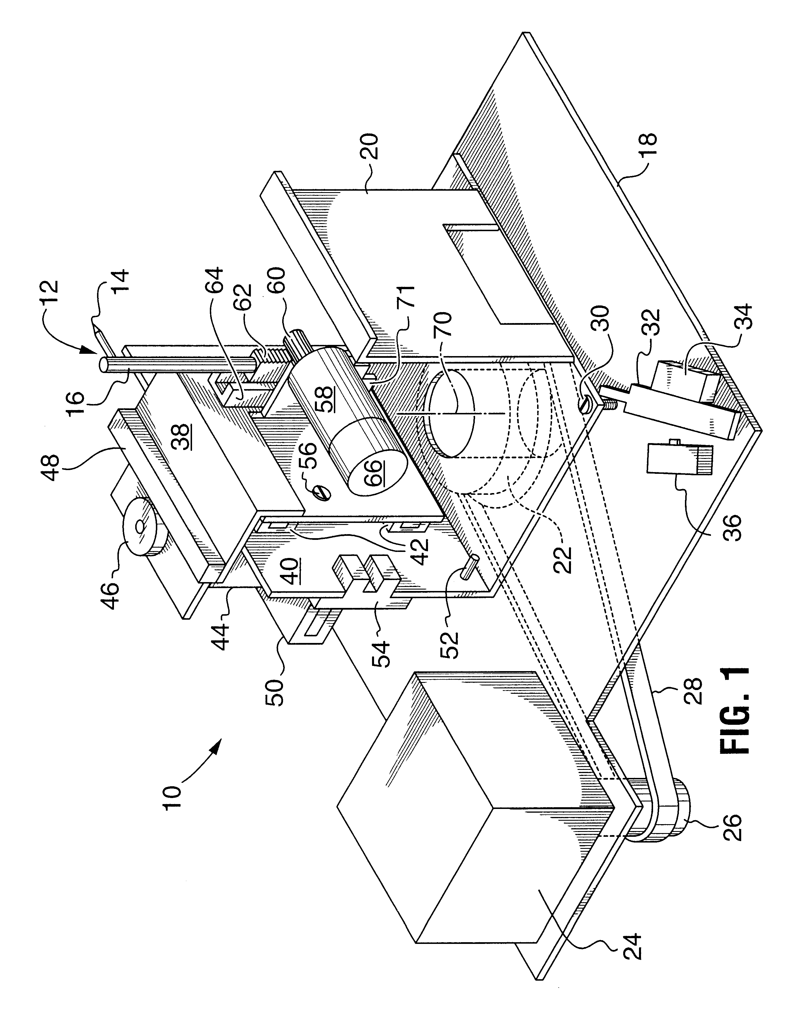
FIG. 1 shows a perspective view of a preferred embodiment of a tracer stylus actuator apparatus depicted generally by reference number 10. Apparatus 10 positions stylus 12 at desired points in 3-dimensional space and produces the coordinates of the position of stylus 12 to enable the spatial location of either the end point 14 of the stylus 12 or the backside 16 of stylus 12 to be determined.

The stylus actuator 10 is mounted on a base 18 which remains stationary. Rotatably connected to base 18 is an intermediate frame or turntable 20 by means of a pulley and bearing assembly 22. The rotation of intermediate frame or turntable 20 with respect to base 18 around pulley and bearing assembly 22 is controlled by rotation motor 24 which drives pulley 26 connected to bearing and pulley assembly 22 by means of a belt 28. The rotation motor 24 preferably is a stepper motor. Using a stepper motor allows the control of the rotation effected by rotation motor 24 by discrete rotational steps ther...


PUM


Abstract

Apparatus for tracing the perimeter shape of the lens holding aperture of an eyeglass frame, or an eyeglass lens, includes a holder to releasably hold an eyeglass frame or lens for tracing measurement. A tracing stylus has a 3 axis movement control apparatus to move the stylus around an axis of rotation and in a vertical and a horizontal direction of a plane rotatable about the axis of rotation. The stylus is urged into horizontal contact with the frame or lens to be traced by a horizontal axis motor dynamically controlled to optimize the contact force between the tracing stylus and frame or lens during the trace process. Control of the vertical movement axis of the stylus optimally provides a weightless behaviour of the stylus permitting it to move vertically responsive to external vertical forces.

Description

This invention relates to a computerised tracing apparatus used to trace the perimeter of eyeglass frames and lenses to determine the shape of the lenses or frames.BACKGROUND TO THE INVENTIONEyeglass frames are produced in a wide variety of shapes depending on the design of the frames. The corresponding eyeglass or ophthalmic lenses that will be mounted in the eyeglass frames must be shaped to have a conforming perimeter corresponding to the frame into which they will be mounted.Generally, ophthalmic lenses are produced with various optical correction factors and have a uniform perimeter shape when produced and are termed lens blanks. A person will select the eyeglass frame most pleasing to him or her and, typically, it is the function of an optical dispensary to shape the lenses blanks to conform or fit into the particular selected eyeglass frame. Once the lens blanks have been shaped, they are mounted in the eyeglass frame and ready to wear.In the past, the lens grinders which are...

Claims


Application Information

Patent Timeline
Patent Type & Authority Patents(United States)
IPC IPC(8): B24B9/14B24B9/06G02C13/00
CPCB24B9/144G02C13/003
Inventor KUJAWA, S. KIM
Owner 6338631 CANADA
Why Eureka
Try Eureka