
Overflow drain outlet cover system

a drain outlet and cover technology, applied in the direction of roof drainage, functional valve types, lighting and heating apparatus, etc., can solve the problems of unsafe or unsanitary conditions, unsightly pipe outlet openings, and detracting from the building appearance,

Inactive Publication Date: 2002-11-05
BROWN KENNETH E +1
View PDF14 Cites 15 Cited by
  • Summary
  • Abstract
  • Description
  • Claims
  • Application Information

AI Technical Summary

Benefits of technology

It is a further object and feature of the present invention to provide such a system which allows the drain pipe outlet cover to be painted or coated with a material and / or color that blends in with the building exterior.
It is still another object and feature of the present invention to provide such a system which provides a simple installation.
According to a preferred embodiment of the present invention, there is provided a pipe cover system for a pipe end opening of a wall drain outlet pipe, comprising, in combination: a cover structured and arranged to substantially cover the wall drain outlet pipe end opening; an attacher structured and arranged to attach such cover to the pipe end opening; and a cover opening system structured and arranged to allow flowing water to open such cover sufficiently to allow flowing water to pass from the pipe end opening. It also provides such a system further comprising a restrictor structured and arranged to assist in restricting unwanted matter from entering the pipe end opening. And, it provides such a system wherein such cover opening system comprises at least one rotator structured and arranged to rotatedly open such cover sufficiently to allow flowing water to pass from the pipe end opening. Further, it provides such a system wherein such rotator comprises at least one hinge structured and arranged to hingedly connect such cover to such attacher.
Additionally, it provides such a system wherein at least one surface of such cover is structured and arranged to be bondable to a coating; and, wherein such at least one surface of such cover is structured and arranged to be bondable to a cementitious coating. Also, it provides such a system wherein such at least one surface of such cover is structured and arranged to be bondable to a paint coating. Further, it provides such a system wherein such cover and such at least one hinge are structured and arranged such that such at least one hinge supports such cover at a cover top portion and allows rotation of such cover outwardly in such manner that when flowing water gravitates from such pipe to such cover, such cover swings open sufficiently to allow flowing water to pass from the pipe end opening. Even further, it provides such a system wherein at least one surface of such cover is structured and arranged to be bondable to a coating. Still further, it provides such a system wherein such attacher further comprises a clamp structured and arranged to substantially engage a circumference of the pipe end opening and be tightened around the pipe end opening.
According to another preferred embodiment of the present invention, there is provided a pipe cover system for a pipe end opening of a wall drain outlet pipe, comprising, in combination: a cover structured and arranged to cover the pipe end opening, wherein a surface of such cover is structured and arranged to be bondable to a coating; and at least one hinge structured and arranged so that such at least one hinge, when attached with the pipe end opening, supports such cover at a cover top portion and allows rotation of such cover outwardly in such manner that when flowing water gravitates from the wall drain outlet pipe to such cover, such cover swings open sufficiently to allow flowing water to pass from the pipe end opening. It also provides such a system further comprising a circular band with an adjustable tightener, such band being structured and arranged to be tightened around an external surface of the wall drain outlet pipe adjacent the pipe end opening.
Additionally, it provides such a system wherein such hinge connects such cover with such circular band. And, it provides such a system further comprising a restrictor attached to such circular band, such restrictor being structured and arranged to assist in restricting unwanted matter from entering the pipe end opening. It also provides such a system wherein: such restrictor comprises at least one round bar; and wherein such cover has a diameter about two inches greater than a diameter of the pipe.

Problems solved by technology

The pipe outlet openings are unsightly and detract from the building appearance.
Debris, vermin and even children may enter these uncovered pipe outlets, potentially blocking them or providing an unsafe or unsanitary condition.

Method used


Image

  • Overflow drain outlet cover system
  • Overflow drain outlet cover system
  • Overflow drain outlet cover system

Examples


Embodiment Construction

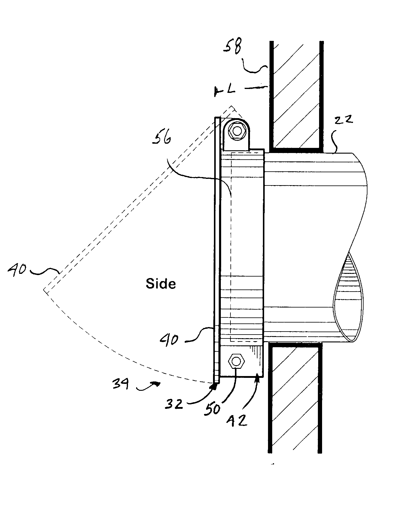
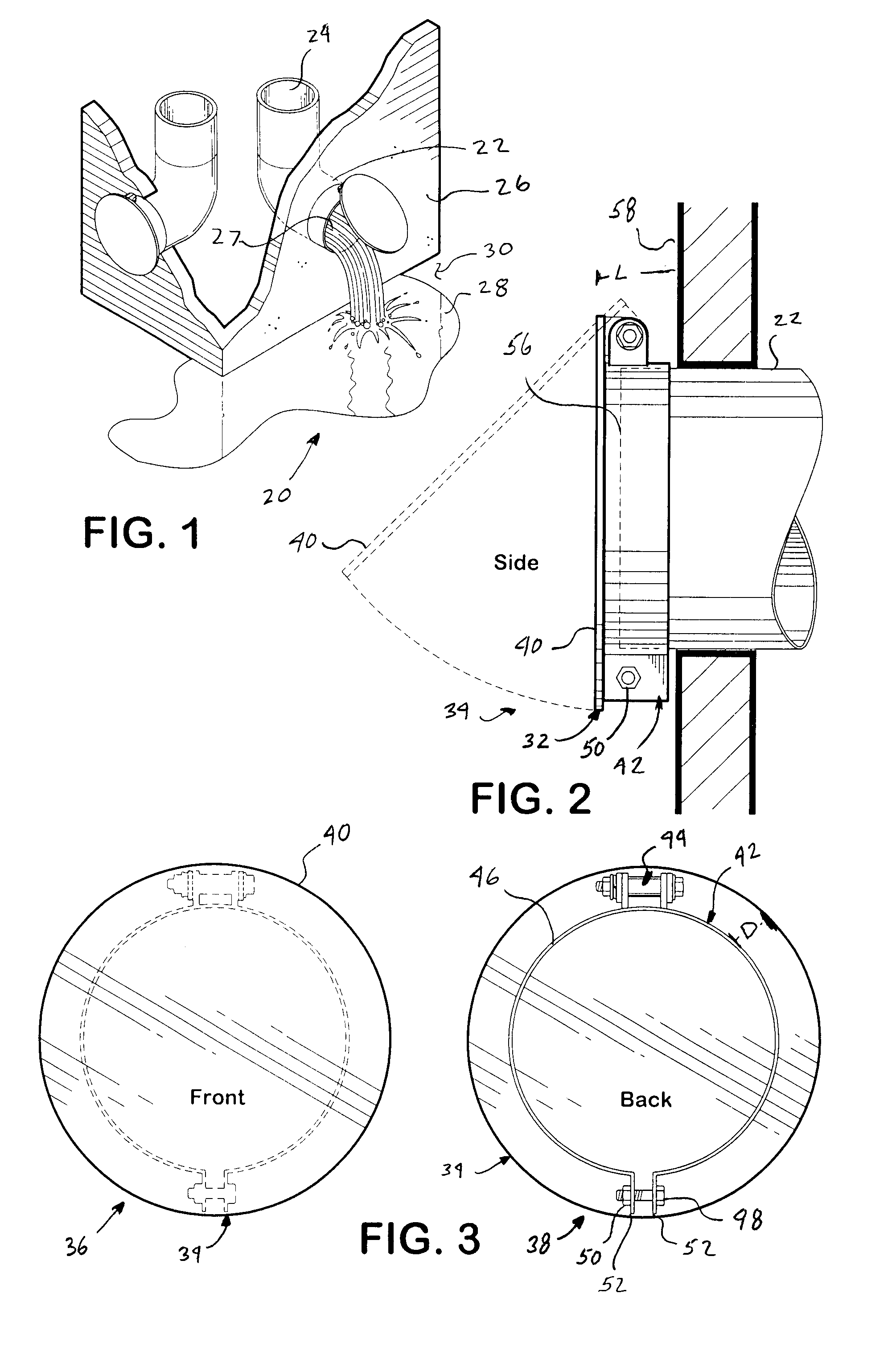
FIG. 1 is a perspective view of the overflow drain outlet cover system 20 illustrated in a typical use, installed on a pipe 22, extending from the down-spout 24 of preferably, a roof drain, installed along the inside portion of a building (embodying herein a building substantially enclosing such wall drain outlet pipe) and extending through the exterior side of a building 26 (embodying herein wherein such pipe end opening is situated at an exterior wall location of such building), according to a preferred embodiment of the present invention. Preferably, the pipe 22 extends such that the pipe and pipe opening 27 (embodying herein a wall drain outlet pipe having a pipe end opening) are at least two inches beyond the building 26. The down-spout 24 may also extend from a fire sprinkler system or other system where water 28 is to be released to the building exterior 30.

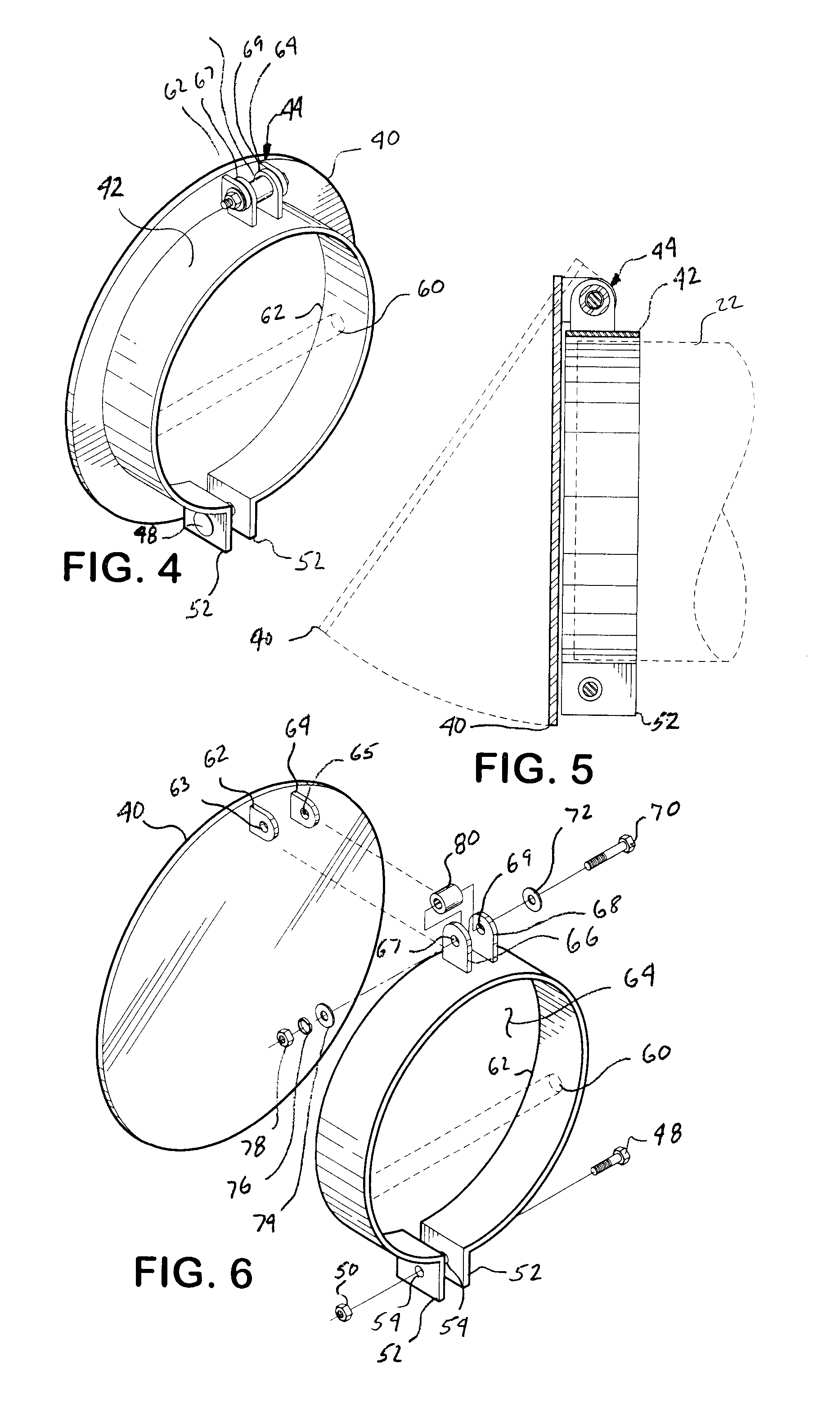
FIG. 2 is a side view, partially in section, of an overflow drain outlet cover 32, according to a preferred embodiment 3...


PUM


Abstract

A system for covering drain pipe outlets, particularly, as they exit a building. The system includes a band that is tightened around the exterior of a pipe as it protrudes through the side of a building. Attached to the band is a hinged cover which is sized to entirely cover the pipe and hidden hinge. The cover may be covered with material to match or complement the building exterior surfacing, such as paint or stucco. In addition, the band portion may also include one or more restictors, such as bars, to prevent unauthorized access or debris from entering the pipe. The system provides for multiple size covers and bands for a wide variety of pipe sizes.

Description

This invention relates to providing a system for covering a wall drain outlet pipe, extending from the exterior wall of a building, while allowing water flow from the pipe. In addition, the system provides for a cover having a surface which is bondable to a coating in order to provide a more aesthetically pleasing building exterior.Typically, drain pipe outlets are used to allow water to be drained either from a building rooftop, or a system within the building, such as a fire sprinkler system or an air conditioning system. Typically, drain pipe outlets range in size from about 2 inches in diameter up to about 24 inches in diameter. They typically exit the side of a building structure through a wall, thereby allowing the water to flow towards a designated drainage area. The great majority of these drain pipe outlets are roof drain outlets. Roof drain outlets typically extend from the roof down through the inside of the building to a point roughly twelve inches above ground, where th...

Claims


Application Information

Patent Timeline
Patent Type & Authority Patents(United States)
IPC IPC(8): E04D13/08E04D13/04
CPCE04D13/08E04D2013/0806Y10T137/698Y10T137/7902
Inventor BROWN, KENNETH E.BROWN, CINDY K.
Owner BROWN KENNETH E
Learn More