

Electrical energy depletion/collection system
a technology of electric energy depletion and collection system, applied in the direction of aircraft static dischargers, transportation and packaging, lighter-than-air aircraft, etc., can solve the problems of limited success of prior art attempts to harness electrical energy from lightning or electrical charges produced in storms, and cannot be deployed in areas
- Summary
- Abstract
- Description
- Claims
- Application Information
AI Technical Summary
Benefits of technology
Problems solved by technology
Method used
Image

Examples
Embodiment Construction
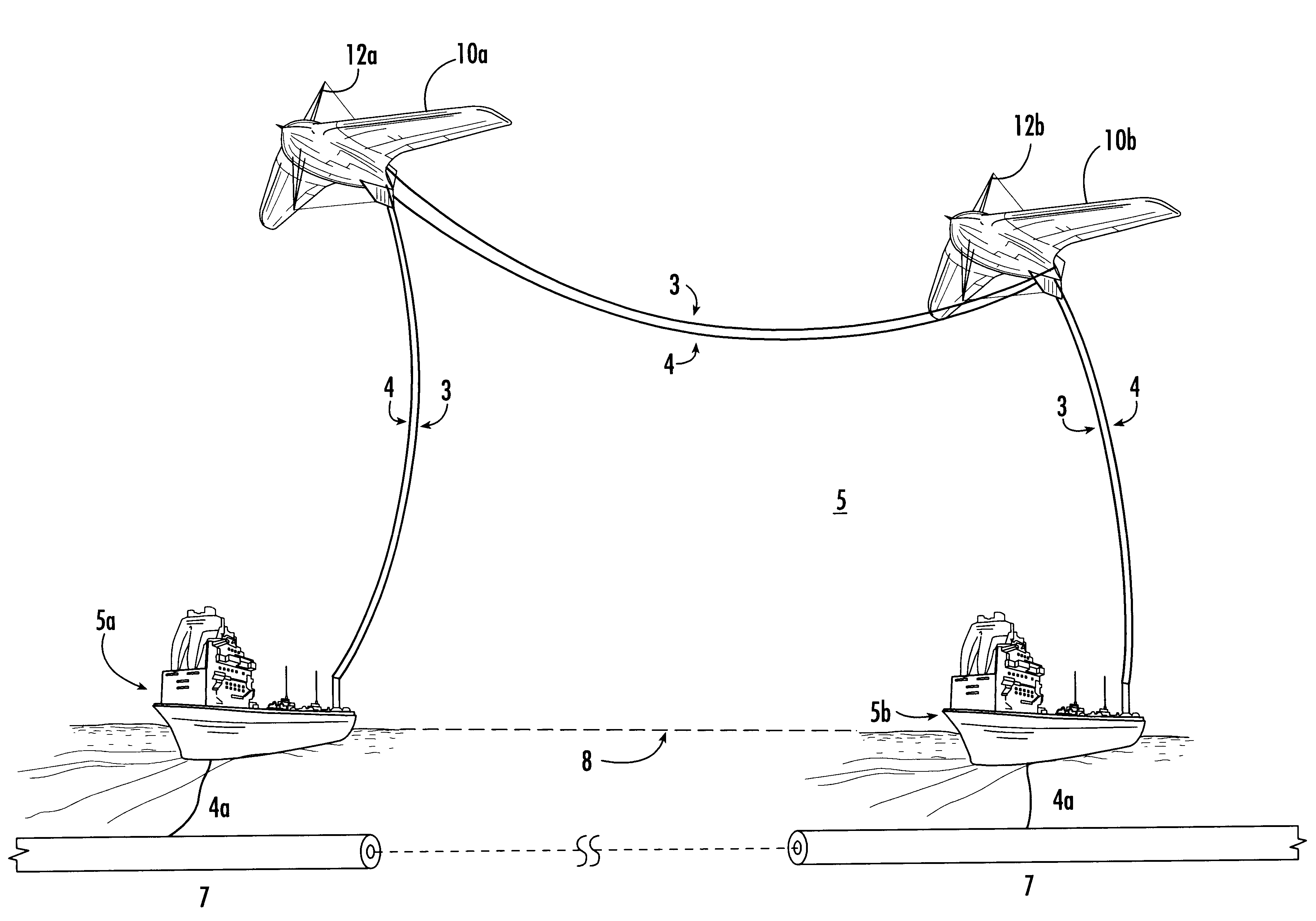
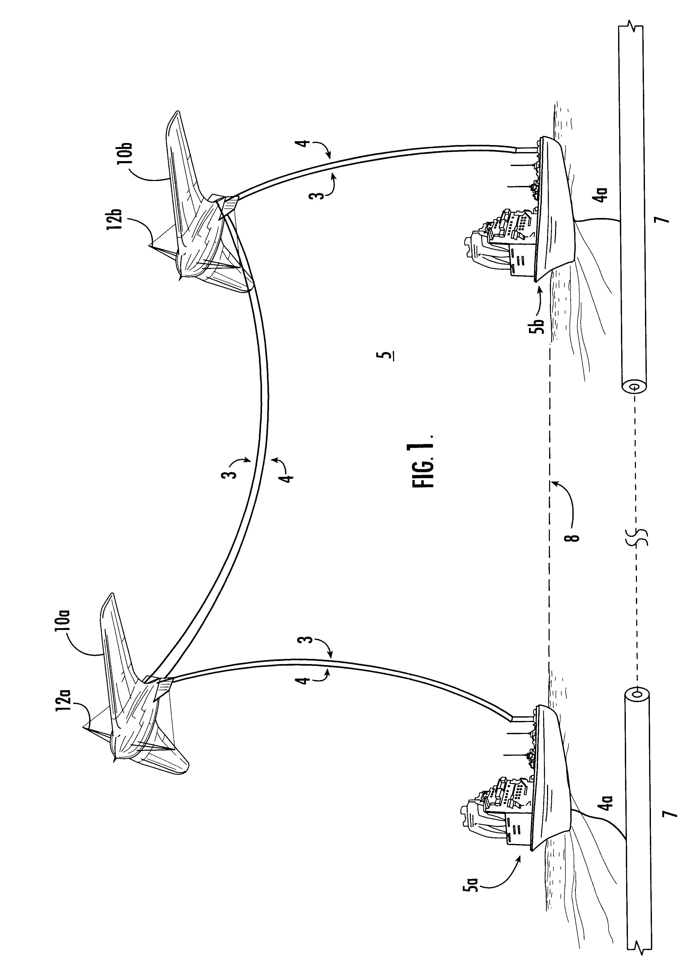
In one embodiment, the electrical energy depletion / collection system 5, FIG. 1, of the subject invention includes mobile host platform or platforms 5a and 5b, in this embodiment, ships, but they could also be submarines, trains, tractor trailer trucks, or even airplanes.
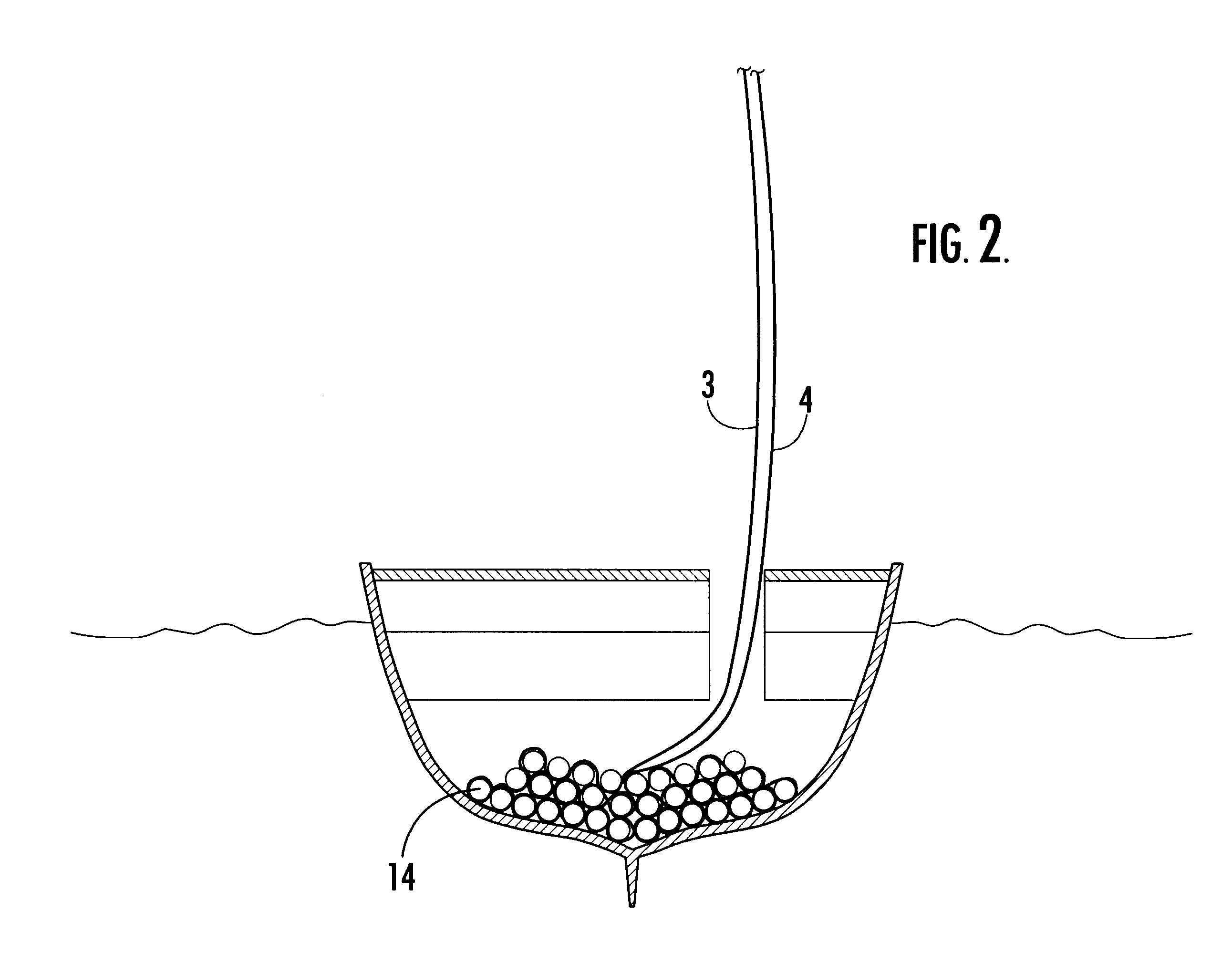
System 5 also includes a mobile airborne trigger platform or platforms 10a, 10b which, in the preferred embodiment, are dirigibles but which could also be laser probes, rockets, kites, or the like. Such a dirigible may be elasteometrical and aerodynamic in design and constitutes a vessel with 2-3 times the volume of the Hindenberg but shaped like a flying wing capable of using jet or turboprop engines for propulsion and braking. There is typically an electrical and physical connection between mobile host platforms 5a and 5b and airborne trigger platforms 10a and 10b such as superconducting cables 3 and 4. System 5 also includes an electrical energy storage subsystem resident on at least one of the mobile airborne tri...
PUM
 Abstract
Description
Claims
Application Information