Plasma torch, plasma torch nozzle, and plasma-working machine

a plasma torch and nozzle technology, applied in the field of plasma torch, can solve the problems of increasing the contact resistance between the nozzle and the nozzle seat, affecting the formation of reliable electroconductive paths, and melting of the contact surface between the two, so as to improve the surface area of the nozzle, improve the effect of nozzle nozzle nozzle, and facilitate removal

Active Publication Date: 2010-06-24
KOMATSU IND CORP
View PDF5 Cites 30 Cited by
  • Summary
  • Abstract
  • Description
  • Claims
  • Application Information

AI Technical Summary

Benefits of technology

[0020]According to the aspects described above, an electroconductive path for a pilot arc is reliably formed. Also, according to the aspects described above, the nozzle can be readily removed when the nozzle is to be replaced because the electric contact portion generates a force that pushes the nozzle outward from the torch main unit.
[0021]In an aspect of the present invention, restoration is readily achieved because the components that can be damaged are the nozzle and the electric contact portion, and one or both can be replaced when poor contact occurs in a case that the electric contact portion can be removed from the torch main unit. Also, in an aspect of the present invention, only the contact between the nozzle and the electric contact portion provides an electrical connection between the nozzle and the electroconductive path for a pilot arc. The force that the electroconductive path applies to the nozzle is merely the pressing force from the electric contact portion, and since the force is substantially parallel to the center axis of the nozzle, the force does not interfere with the positioning of the center axis of the nozzle.
[0022]A nozzle according to yet another aspect adapted to be installed in a plasma torch and includes a first cylindrical part, an outer flange, and a second cylindrical part. The outer flange has an electroconductive surface protruding from the external peripheral surface of the first cylindrical part in the radial direction. The outer flange is disposed adjacent to the first cylindrical part in the axial direction, and has a greater outer diameter than the first cylindrical part. The second cylindrical part is disposed adjacent to the outer flange in the axial direction, has a knurled pattern formed on the external peripheral surface, and has a smaller outer diameter than the outer flange. When this nozzle is incorporated into a plasma torch, the electric contact portion provided in the torch main unit makes contact with the electroconductive surface of the nozzle and press against the electroconductive surface of the nozzle due to the elastic force of the electric contact portion. In this case, the pressing force from the electric contact portion acts on the electroconductive surface in a direction substantially parallel to the center axis of the nozzle because the electroconductive surface protrudes in the radial direction from the external peripheral surface of the first cylindrical part. Accordingly, the center axis of the nozzle is unlikely to become offset from the correct position, even when the elastic force of the electric contact portion is nonuniform. The electroconductive path for the pilot arc to the nozzle can thereby be more reliably formed. With the nozzle, a large-diameter flange is provided to thereby increase the surface area of the nozzle. Furthermore, a knurled pattern is formed on the external peripheral surface of the second cylindrical part, whereby the surface area of the nozzle is increased. Therefore, the cooling effect of the nozzle can be improved.

Problems solved by technology

However, the first type of contact has the following problem.
The reaction force when the O-ring is compressed reduces the force that presses the nozzle against the nozzle seat, and interferes with the formation of a reliable electroconductive path.
Therefore, the contact resistance between the nozzle and the nozzle seat may be increased, and the contact surface between the two may be melted by sparks generated by poor contact.
Since the electrical insulation is more readily damaged in air than in water, sparks more readily occur between the nozzle and the nozzle seat on the gas channel side than in the coolant channel side.
The torch main unit, which is not usually an expendable part, is damaged when such a spark occurs.
It is not easy for the user to remove the nozzle by hand in a simple manner because of this strong holding force when the nozzle is to be replaced.
Therefore, the center axis of the nozzle may become misaligned from the correct position (typically, the center axis position of the torch) due to the unbalanced elastic force of the plurality of electric contacts.

Method used


Image

  • Plasma torch, plasma torch nozzle, and plasma-working machine
  • Plasma torch, plasma torch nozzle, and plasma-working machine
  • Plasma torch, plasma torch nozzle, and plasma-working machine

Examples


Embodiment Construction

[0030]An embodiment of the present invention is described below with reference to the drawings.

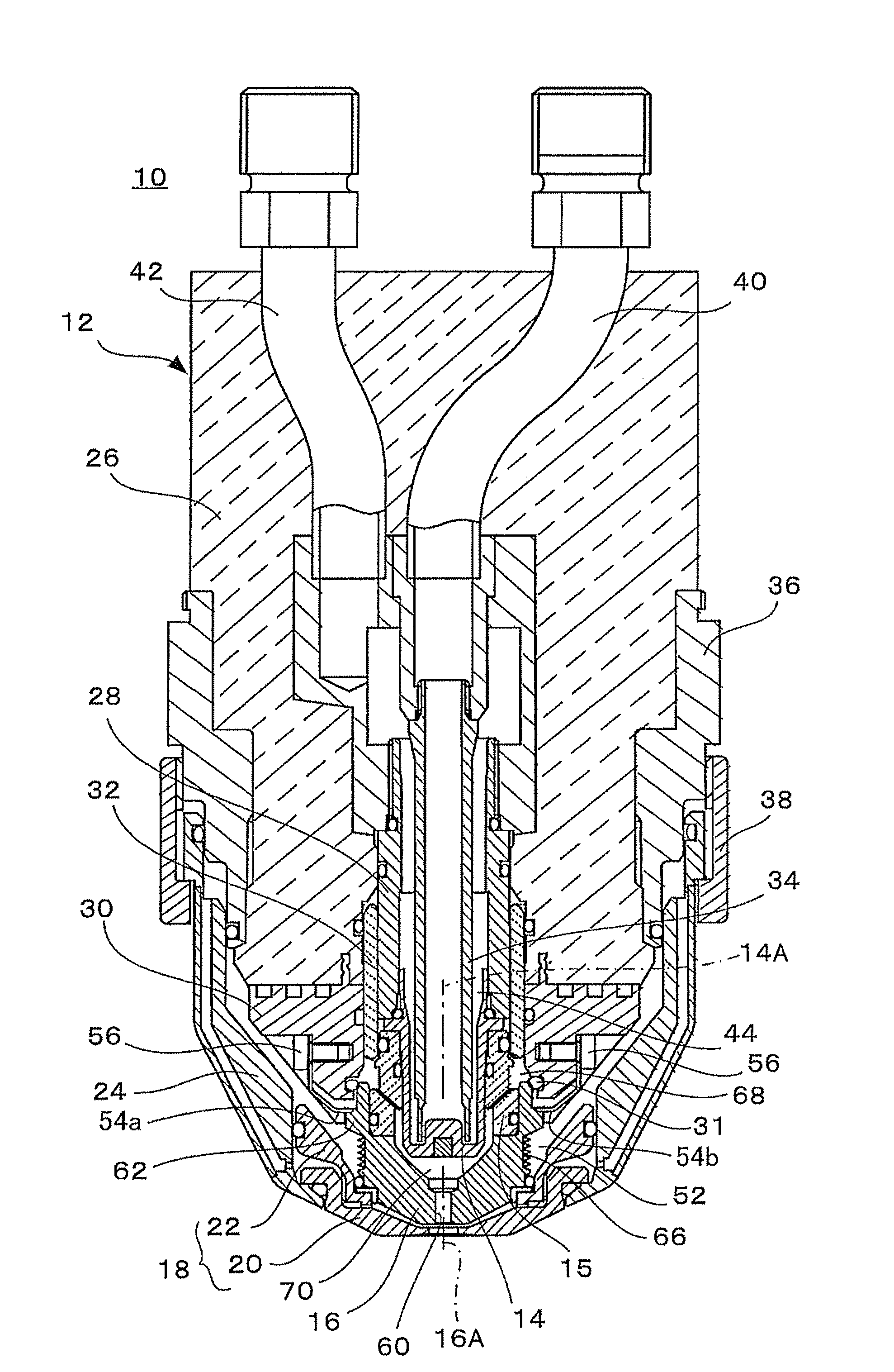
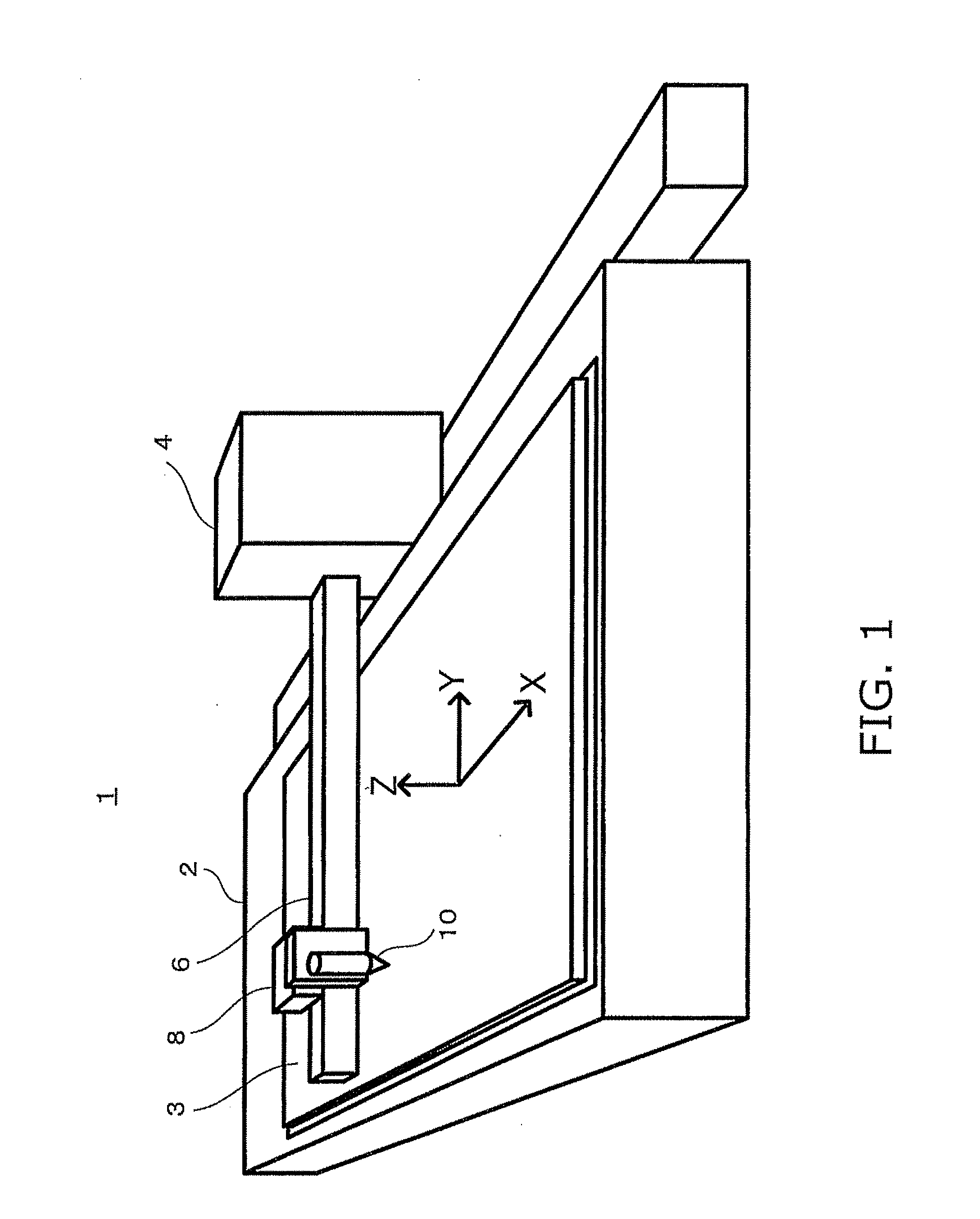
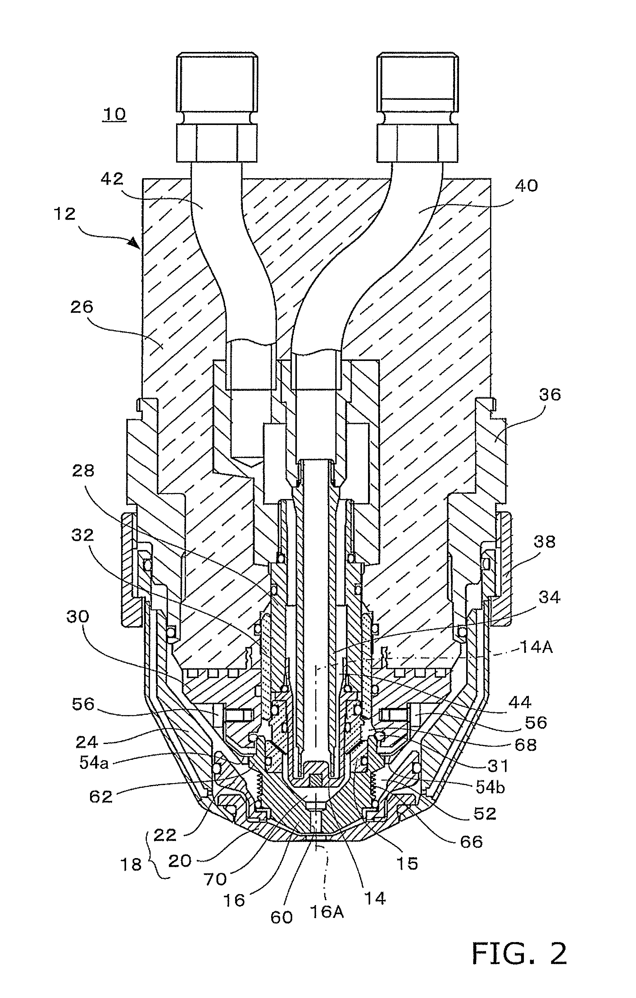
[0031]FIG. 1 shows in a simplified manner the overall configuration of an embodiment of the plasma-working machine according to the present invention.

[0032]A plasma-working machine (e.g., a plasma cutter) 1 is provided with a table 2 on which a workpiece (typically, a steel plate) 3 is arranged; a plasma torch 10 for emitting a plasma arc and working (e.g., cutting) a workpiece 3; torch movement devices 4, 6, 8 for moving the plasma torch 10 in the X (lengthwise), Y (transverse), and Z (height) directions with respect to the workpiece 3; and other components, as shown in FIG. 1. The torch movement devices 4, 6, 8 are composed of, e.g., a movement truck 4 that can move in a reciprocating fashion in the X direction adjacent to the table 2; an arm 6 extending above the table 2 from the movement truck 4 in the Y direction; a carriage 8 that movably supports the plasma torch 10 in a reciprocati...


PUM

PropertyMeasurementUnit
electroconductiveaaaaaaaaaa
outer diameteraaaaaaaaaa
structureaaaaaaaaaa

Abstract

A plasma torch includes a torch main unit and a nozzle. The torch main unit has a nozzle seat member on which the nozzle is mounted. The nozzle is arranged to move toward or away from the nozzle seat member in a direction substantially parallel to a center axis of the nozzle when the nozzle is mounted on or removed from the nozzle seat member. The nozzle has an electroconductive surface facing the nozzle seat member. The torch main unit has an elastic electric contact portion contacting with the electroconductive surface of the nozzle to form an electroconductive path for a pilot arc to the nozzle. The electroconductive surface of the nozzle presses the electric contact portion in the direction substantially parallel to the center axis when the nozzle is moved toward the nozzle seat member to mount the nozzle on the nozzle seat member.

Description

CROSS-REFERENCE TO RELATED APPLICATIONS[0001]This national phase application claims priority to Japanese Patent Application No. 2007-183558, filed on Jul. 12, 2007. The entire disclosure of Japanese Patent Application No. 2007-183558 is hereby incorporated herein by reference.TECHNICAL FIELD[0002]The present invention generally relates to a plasma-working machine such as a plasma cutter, and particularly relates to a plasma torch thereof, and to the structure of the nozzle thereof.BACKGROUND ART[0003]A plasma torch generates an electrical discharge referred to as a pilot arc between an electrode and a nozzle inside a torch, moves the pilot arc, and establishes a plasma arc, which is an electrical discharge between a workpiece and an electrode for cutting the workpiece, when cutting or other work is started. An electroconductive path for generating the pilot arc extends inside the torch from the torch main unit to the nozzle.[0004]A typical example of a conventional structure of an e...

Claims


Application Information

Patent Timeline
Patent Type & Authority Applications(United States)
IPC IPC(8): B23K10/00
CPCH05H1/34H05H2001/3457H05H2001/3426H05H1/3421H05H1/3457H05H1/3423B23K10/00H05H1/28
Inventor YAMAGUCHI, YOSHIHIROKURAOKA, KAZUHIRO
Owner KOMATSU IND CORP
Why Eureka
Try Eureka