Link chain

a technology of pintle chain and link chain, which is applied in the direction of chain elements, belt/chain/gearing, chain elements, etc., can solve the problems of patented chain exhibiting certain drawbacks, affecting the actual use of the chain, and changing the transmission ratio as well as uninterrupted transmission of torqu

Inactive Publication Date: 2002-11-12
LUK LAMELLEN & KUPPLUNGSBAU BETEILIGUNGS KG
View PDF21 Cites 37 Cited by
  • Summary
  • Abstract
  • Description
  • Claims
  • Application Information

AI Technical Summary

Benefits of technology

An object of the invention is to provide a novel and improved link chain or pintle chain which is constructed and assembled in such a way that it is sturdier, safer, quieter and not bulkier than heretofore known chains.

Problems solved by technology

Since the length of the link chain is fixed, the just described simultaneous adjustments of the two axially movable flanges necessarily result in a change of the transmission ratio as well as in uninterrupted transmission of torque in the course of the actual selection of a desired speed ratio.
However, the patented chain exhibits certain drawbacks such as excessive vibration in actual use.
Excessive vibration entails the generation of pronounced noise and adversely affects the reliability and safety of the CVT in actual use.
Furthermore, the patented chain is rather bulky which limits its usefulness or necessitates extensive redesigning of parts which embody or cooperate with such transmission.
A drawback of the just described chain is that it also exhibits the tendency to carry out pronounced vibratory movements when in actual use; this adversely affects the smoothness of running as well as the safety of the CVT and results in the generation of excessive noise.
In addition, the components of the composite links in the patented chain undergo pronounced deformation and / or exhibit other undesirable defects after a relatively short period of actual use.
It has been ascertained that, though the just described patented link chain holds the rocker elements against axial shifting transversely of the chain, this chain still exhibits several drawbacks such as pronounced vibration in actual use and the afore-discussed undesirable consequences, e.g., the generation of noise, reduced stability and / or others.

Method used


Image

  • Link chain
  • Link chain
  • Link chain

Examples


Embodiment Construction

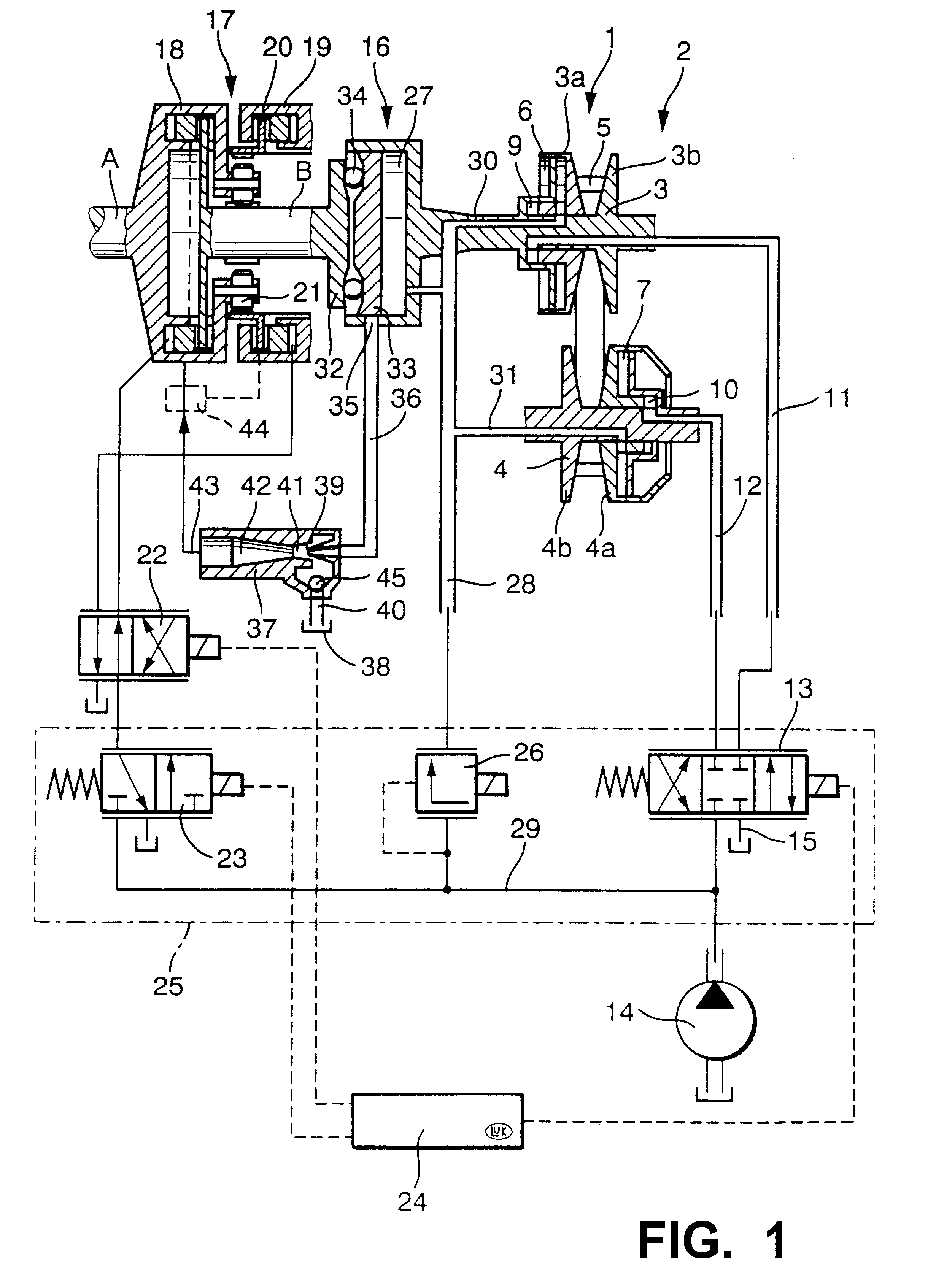
FIG. 1 shows certain details of a power train 1 which can be utilized in a motor vehicle to transmit torque between a prime mover (such as a combustion engine or a hybrid including a motor and an engine) and the front and / or rear wheels. The power train 1 includes a continuously variable transmission (CVT) 2 including a driving pinion or sheave 3, a driven pinion or sheave 4 and an endless flexible element 5 (namely a link chain or a pintle chain) which is constructed and assembled in accordance with the present invention.

The pulley 3 comprises an axially fixed conical flange 3b and an axially movable (adjustable) conical flange 3a. Analogously, the driven pulley 4 comprises an axially fixed conical flange 4b, and an axially movable conical flange 4a. The chain 5 has arcuate portions trained over the two pulleys, i.e., one of such arcuate portions is disposed between the flanges 3a, 3b and the other arcuate portion is disposed between the flanges 4a, 4b.

A first adjusting unit 6 serv...


PUM


Abstract

An endless link chain, particularly for use in a continuously variable transmission in the power train of a motor vehicle, has composite links and pintles which articulately connect neighboring links to each other. At least one of the links is assembled of at least two types of parallel plate-like components which differ from each other in size, shape, material and/or strength. The purpose of such selection of the plate-like components is to enhance one or more characteristics of the chain, for example, to reduce or eliminate vibration, to reduce the bulk and/or to properly position the pintles. The distribution of components in one or more links can be selected with a view to influence the above-enumerated and/or other characteristics, such as the resistance to deformation, of the chain.

Description

The invention relates to improvements in endless flexible torque transmitting devices, and more particularly to improvements in so-called link chains (also known as pintle chains) which can be trained over and can transmit torque between driving and driven rotary parts, for example, over two or more adjustable pulleys or sheaves forming part of an infinitely or continuously variable transmission (CVT) in the power train of a motor vehicle.A link chain of the above outlined character normally comprises a series of composite links each of which extends transversely of the chain and each of which can comprise a group or array of plate-like components. The components have openings for pintles which extend transversely of the chain and each of which articulately connects two successive links to each other so that the thus coupled links can pivot with respect to one another. Reference may be had, for example, to U.S. Pat. No. 5,427,583 (granted Jun. 27, 1995 to Wolf for "LOW-NOISE, TRIPLE...

Claims


Application Information

Patent Timeline
Patent Type & Authority Patents(United States)
IPC IPC(8): F16G5/18F16G5/00F16H9/02F16H9/18F16G13/06F16G13/02
CPCF16G5/18F16H9/18
Inventor GREITER, IVO
Owner LUK LAMELLEN & KUPPLUNGSBAU BETEILIGUNGS KG
Why Eureka
Try Eureka