Method and apparatus for maintaining the alignment of a fuel injector

a fuel injector and alignment technology, applied in mechanical equipment, liquid fuel feeders, machines/engines, etc., can solve the problems of affecting emissions, reducing the performance of the engine, and wetting the wall,

Inactive Publication Date: 2002-11-19
COOPER STANDARD AUTOMATIVE INC
View PDF8 Cites 64 Cited by
  • Summary
  • Abstract
  • Description
  • Claims
  • Application Information

AI Technical Summary

Benefits of technology

In yet another embodiment of the present invention, a method for maintaining the alignment of a fuel injector relative to a fuel rail cup having an annular flange is provided. The method comprises the steps of positioning inwardly biased tangs on a retaining clip to apply pressure to the sides of the annular flange and preventing the axial rotation of the fuel injector by utilizing an alignment protrusion to align with a slot in the annular flange and apply pressure to the sides of the annular flange.

Problems solved by technology

If a fuel injector is not properly aligned with an intake port, wall wetting can result.
This results in reduced performance of the engine and adversely affected emissions.
During the shipping process, fuel injectors are subjected to forces that can cause them to rotate and in some cases, even become dislodged from the fuel rails.
While this method prevented the injector from becoming dislodged and prevented some shifting, these early clips did not significantly prevent rotational movement of the injector in relation to the fuel rail cup during shipping.
This design was not compatible with certain materials used for fuel rails, especially composites and aluminum.
However, this method did not significantly prevent axial rotation of the injector in relation to the fuel rail cup and since pressure was applied directly to the side of the fuel rail, certain materials could not be used to construct the fuel rail.
However, the fuel injector can still shift enough to affect alignment, and thus affect emissions and performance of the engine.

Method used


Image

  • Method and apparatus for maintaining the alignment of a fuel injector
  • Method and apparatus for maintaining the alignment of a fuel injector
  • Method and apparatus for maintaining the alignment of a fuel injector

Examples


second embodiment

FIG. 8 shows the retaining clip 72 of the present invention. This embodiment shares the same features as the embodiment shown in FIG. 7 except for a variation in the design of the alignment protrusion 74. In this embodiment, the alignment protrusion 74 preferably extends from the underside 76 of the flat base 78 of the retaining clip 72. The shape of the alignment protrusion 74 is similar to the shape of the tangs 80 which extend from the flat base 78 of the retaining clip 72. The alignment protrusion 74 is under spring tension and provides bias toward the center of the opening 82 in the retaining clip 72. This embodiment has the advantage of simplified construction, as the rectangular opening 70 as shown in FIG. 7 does not need to be defined in the flat base 78 of the retaining clip 72.

third embodiment

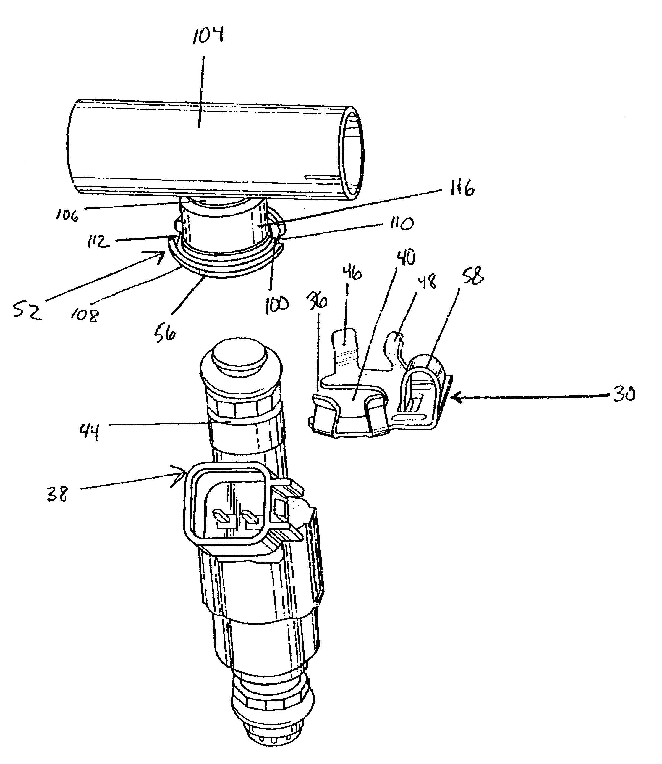
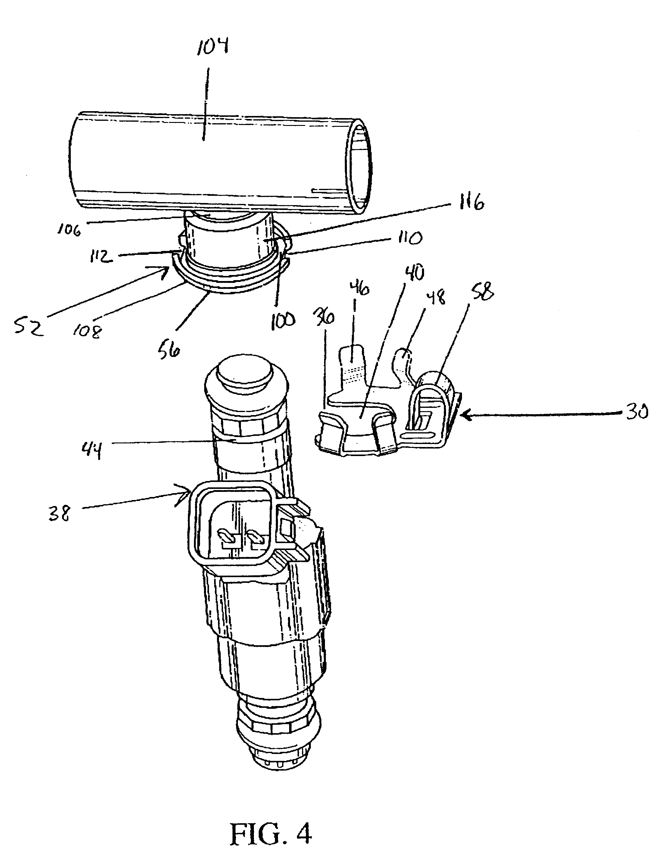
the retaining clip 84 of the present invention is shown in FIG. 9. In this embodiment, the outer edges 86 of the retaining clip 84 are extended to form protrusions 88 that are upstanding from the flat base 90 of the retaining clip 84. Each protrusion 88 has a tang 92 extending towards the flat base 90 of the retaining clip 84 beginning at the upper side 94 of the protrusion 88. Each tang 92 has a flange 96 that extends towards the center of the opening 98 in the retaining clip 84. The tangs 92 are under spring tension and may provide bias toward the center of the opening 98 in the retaining clip 84. The flanges 96 extending from the tangs 92 contact the upper edge 100 of the annular flange 56 on the fuel rail cup 52. These flanges 96 prevent the fuel injector 38 from pulling out of the fuel rail cup 52 once the retaining clip 84 is in place by snapping over the annular flange 56. Since bias may be applied in a direction toward the center of the opening 98 in the retaining clip 84, t...


PUM


Abstract

A method and an apparatus for maintaining the alignment of a fuel injector during shipping and normal use. In one embodiment of the invention, a clip for retaining a fuel injector to a fuel rail cup that has an annular flange is provided. The clip has a substantially flat base to at least partially surround an end of the fuel injector and a plurality of upstanding tangs to receive and substantially surround the annular flange. An alignment protrusion is also provided on the clip to interface with the annular flange to prevent axial rotation of the fuel injector relative to the fuel rail cup.

Description

The invention relates generally to the field of fuel injectors. In particular, this invention relates to a method for maintaining the proper alignment of a fuel injector with a fuel intake port utilizing a retaining clip.DESCRIPTION OF THE RELATED ARTIn modern multi-valve engines utilizing fuel injectors to supply fuel to intake ports, it is important to maintain the proper alignment between the fuel injectors and the corresponding intake ports. In multi-valve engines, it is important to maintain rotational alignment and reduce axial movement of the fuel injector. If a fuel injector is not properly aligned with an intake port, wall wetting can result. Wall wetting occurs when the fuel spray plume from the fuel injector is off-center, and some of the spray contacts the walls of the intake port. This results in reduced performance of the engine and adversely affected emissions. During the shipping process, fuel injectors are subjected to forces that can cause them to rotate and in som...

Claims


Application Information

Patent Timeline
Patent Type & Authority Patents(United States)
IPC IPC(8): F02M55/00F02M69/46F02M61/16
CPCF02M55/004F02M61/168F02M69/465F02M2200/8023F02M2200/803F02M2200/856
Inventor PANASUK, GERARD N.CHATLOS, JAMEY M.COLE, MATTHEW M.PUCCI, PAUL P.MAURER, RAYMOND N.
Owner COOPER STANDARD AUTOMATIVE INC
Why Eureka
Try Eureka