
Diaphragm bellows device

a technology of diaphragm and bellows, which is applied in the direction of bellows, ring springs, springs/dampers, etc., can solve the problems of splinters or fragments of this wafer falling between the diaphragms, trapped in the gaps between the diaphragms, and damage to the diaphragm bellows, etc., to achieve the effect of simple production and assembly

Inactive Publication Date: 2002-11-26
VAT HLDG AG
View PDF3 Cites 24 Cited by
  • Summary
  • Abstract
  • Description
  • Claims
  • Application Information

AI Technical Summary

Benefits of technology

An important object of the invention is to provide a diaphragm bellows device in which the diaphragm bellows is protected against the penetration of parts into the gaps between two adjacent diaphragms so that additional particles are prevented as far as possible from being released into the vacuum when the diaphragm bellows are adjusted. Another object of the invention is to provide a diaphragm bellows device which is simple to produce and assemble and in which the diaphragm bellows are protected against penetration and release of foreign bodies between the adjacent diaphragms.

Problems solved by technology

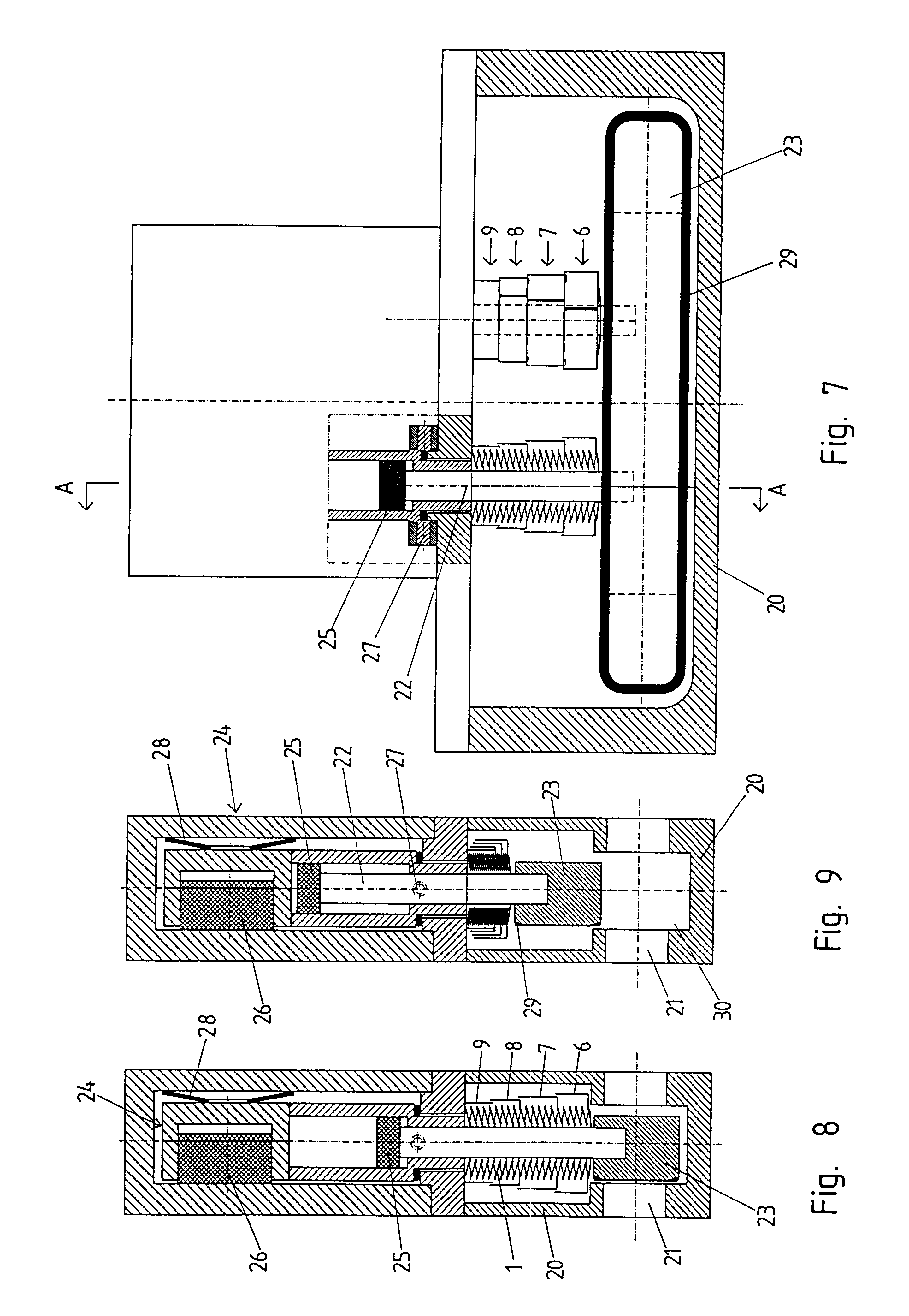
In diaphragm bellows of this kind, when foreign bodies fall into the intermediate spaces located between two adjacent diaphragms at the outer side of the diaphragm bellows and are trapped there, this could damage the diaphragm bellows when contracted, possibly after repeated expansion and contraction processes, so that the diaphragm bellows are no longer tight.
When a wafer breaks while moving through the valve opening, splinters or fragment s of this wafer can fall between the diaphragms and be trapped in the gaps between the diaphragms.
This is disadvantageous particularly in that particles are generated and released in to the vacuum when the telescoping parts of the sleeve are displaced relative to one another.
Also, these telescoping sleeves have a relatively large installed length which can increase space requirements.

Method used


Image

  • Diaphragm bellows device
  • Diaphragm bellows device
  • Diaphragm bellows device

Examples


Embodiment Construction

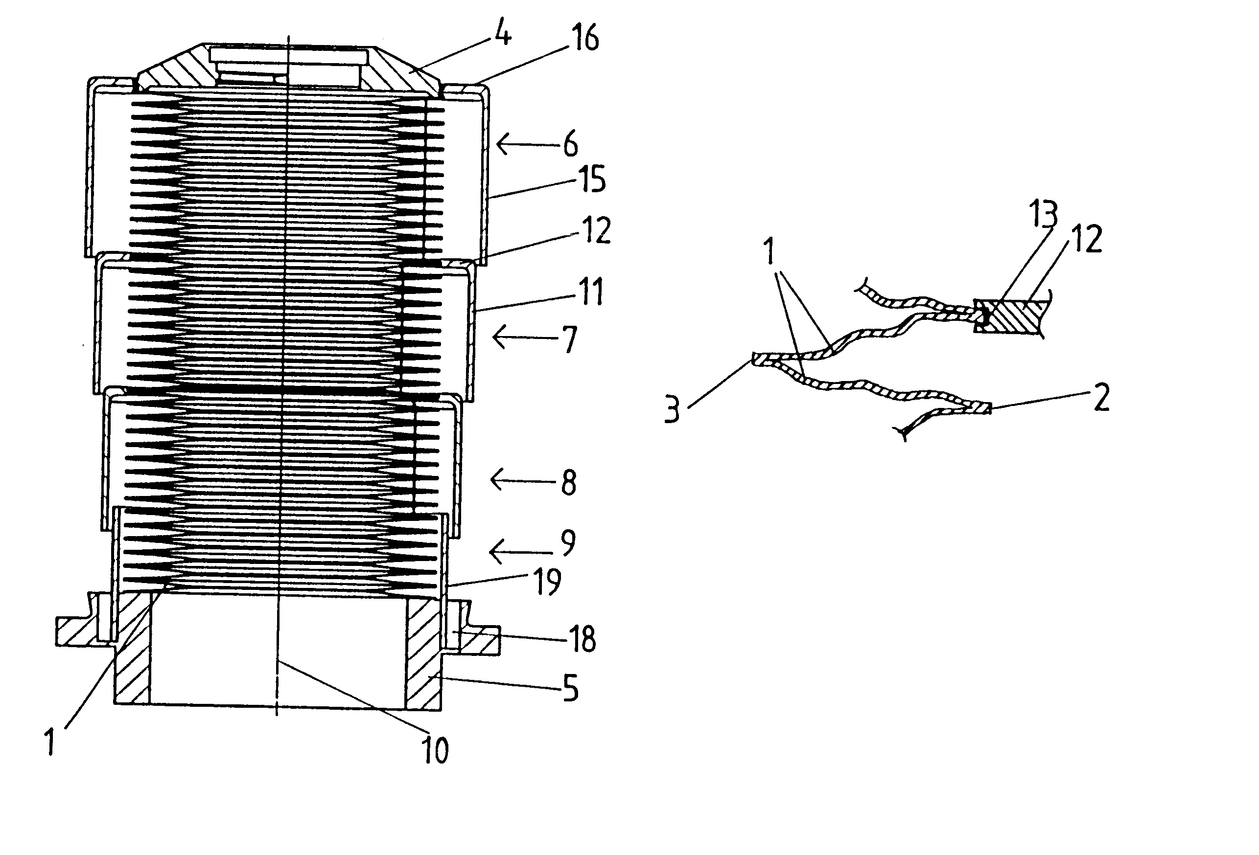
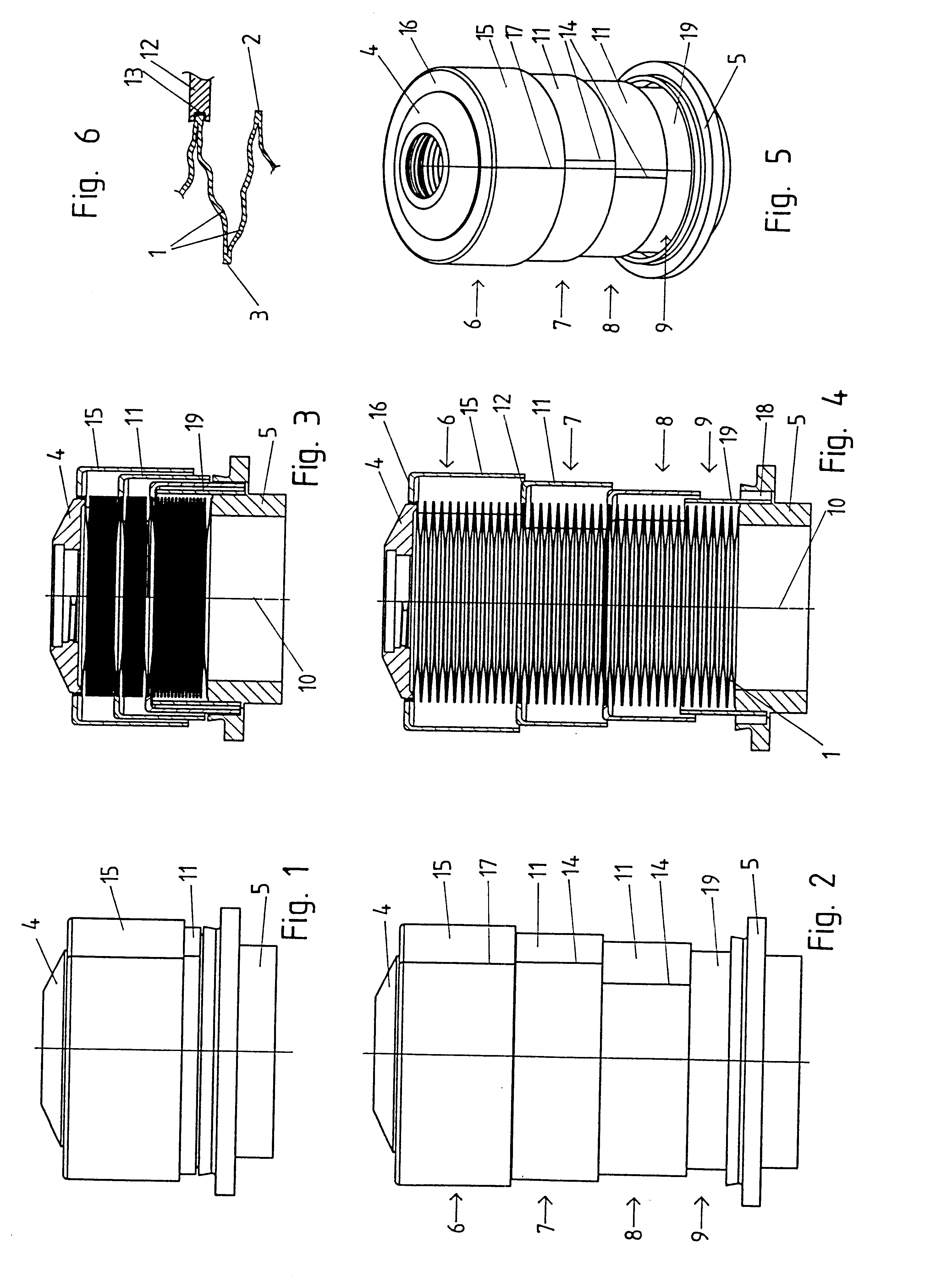
The diaphragm bellows device, according to the invention, shown in FIGS. 1 to 6 has a diaphragm bellows with a plurality of successive annular diaphragms 1 having outer edges 2 and inner edges 3 defining an inner opening of the diaphragm bellows. Successive diaphragms 1 are alternately welded to one another at their outer and inner edges. The two diaphragms 1 at the ends are welded with an end piece 4, 5, respectively, by which the diaphragm bellows can be connected to other parts of a vacuum device, particularly in a vacuum-tight manner. Such diaphragm bellows are known.

A diaphragm bellows device according to the invention further has a plurality of sleeve parts 6 to 9 which enclose the successive diaphragms 1 and which, in their entirety, surround the successive diaphragms along their entire longitudinal extension also in the expanded state of the diaphragm bellows. The sleeve parts 6 to 9 overlap in direction of the longitudinal axis 10 of the diaphragm bellows to a greater or le...


PUM


Abstract

A diaphragm bellows device comprises a diaphragm bellows with a plurality of successive diaphragms which are welded together alternately at the outer and inner edges, wherein the length of the diaphragm bellows can be adjusted between an expanded state and a contracted state, and a plurality of sleeve parts which surround the successive diaphragms and which, together, enclose the successive diaphragms also in the expanded state of the diaphragm bellows over its entire longitudinal extension and overlap to a greater or lesser extent in axial direction of the diaphragm bellows depending on the adjusted length of the diaphragm bellows, wherein at least one of the sleeve parts is held on the welded outer edges of two adjoining diaphragms by a snap connection.

Description

a) Field of the inventionThe invention is directed to a diaphragm bellows device comprising a diaphragm bellows with a plurality of successive diaphragms which are welded together at the outer and inner edges, wherein the diaphragm bellows can be adjusted in length between an expanded state and a contracted state, and comprising a protective device surrounding the successive diaphragms.b) Description of the Related ArtDiaphragm bellows of the type mentioned above, which are used particularly as vacuum leadthroughs, are known in various embodiment forms. For example, these diaphragm bellows are used for sealing actuating stems or spindles inside a housing of a vacuum valve. Diaphragm bellows are adjustable in length between a contracted state and an expanded state. Normally, the device in connection with which the diaphragm bellows is used has a limit for the expansion of the diaphragm bellows which predetermines the completely expanded state of the diaphragm bellows. The maximum len...

Claims


Application Information

Patent Timeline
IPC IPC(8): F16J3/00F16J3/04
CPCF16J3/047F16J3/048
Inventor DUELLI, BERNHARD
Owner VAT HLDG AG
Learn More