Concave optical fiber ferrule holding plate

a holding plate and concave technology, applied in the direction of grinding drives, manufacturing tools, instruments, etc., can solve the problems of affecting the connecting performance of optical fiber connectors, serious affecting the required preciseness of convex curved surfaces, and the bottom surface of the holding plate wears down and releases debris

Inactive Publication Date: 2002-11-26
AWAD ELIAS A
View PDF5 Cites 0 Cited by
  • Summary
  • Abstract
  • Description
  • Claims
  • Application Information

AI Technical Summary

Problems solved by technology

It is well known that the squareness or an error in the tilt angle of the end surface of a polished ferrule with an optical fiber, with respect to a central axis seriously affects the connecting performance of the optical fiber connector.
A ferrule extending too far beyond the surface of its holding plate has a tendency to wobble which seriously affects the required preciseness of the convex curved surfaces.
This problem is further exemplified when the ferrule holding plate is utilized during hand polishing operations.
When polishing an optical fiber end the bottom surface of the holding plate wears down and releases debris as it contacts the polishing material.
This debris contaminates the polishing material and reduces the quality of the polished fiber end face.
Also, holding plates that lock a ferrule in place do not allow the ferrule to float or back off as the holding plate wears.
This in turn will cause an increase in pressure between the end face of the fiber and the polishing material which will ultimately damage the end face of the fiber.
Another problem associated with the flat base type holding plates described above is their inability to measure the degree of degradation or wear on the holding plate.
If the pressure to the holding plate is applied unevenly during use, the plate may ware unevenly.
This uneven wear reduces the operating life of the holding plate and also affects the quality of the fiber optic end face.

Method used


Image

  • Concave optical fiber ferrule holding plate
  • Concave optical fiber ferrule holding plate
  • Concave optical fiber ferrule holding plate

Examples


Embodiment Construction

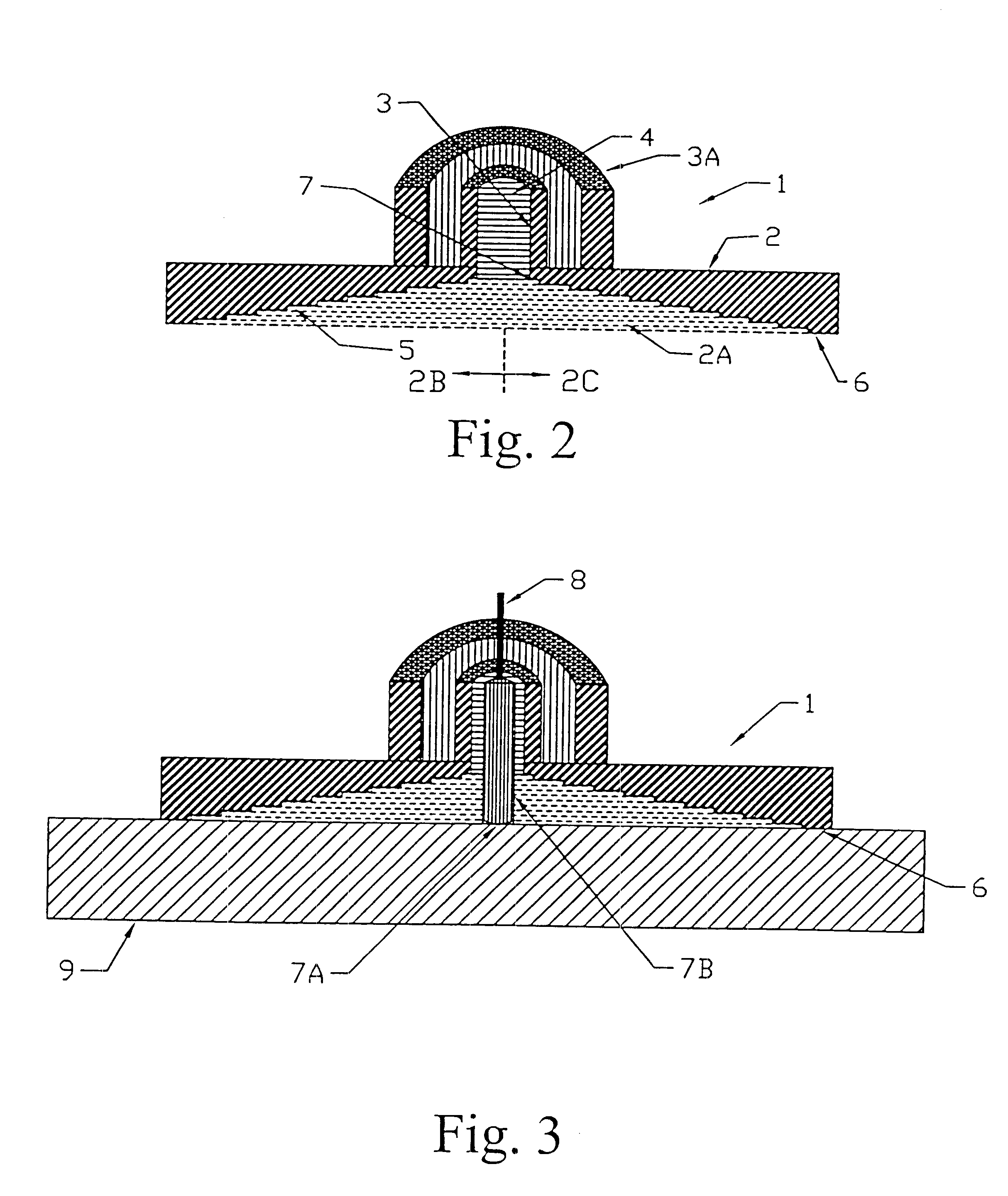
The optical fiber ferrule holding plate of the present invention will be described with reference to FIG. 2. Referring to the cross-sectional illustration of FIG. 2, an optical fiber ferrule holding plate 1 is disclosed. The holding plate 1 is machined from 303 stainless steel, or equivalants thereof, and comprises a circular base section 2, with a concave interior 2A, and a circular ferrule receiving section 3. The ferrule receiving section 3 extends through the center of concave interior 2A and has a ferrule-inserting hole 4 disposed therein. To aid in description of subject invention the cross-sectional illustration of FIG. 2 has a left side 2B and a right side 2C. The receiving section 3 annularly projects concentrically outward from the center of concave interior 2A to a point above base section 2. A surrounding section 3A, located above base section 2 may be added to aid in the holding of holding plate 1 during hand polishing or be used in securing holding plate 1 within a pol...


PUM

PropertyMeasurementUnit
widthaaaaaaaaaa
widthaaaaaaaaaa
widthaaaaaaaaaa

Abstract

A concave optical fiber ferrule holding plate for polishing an end face of an optical fiber is disclosed. The holding plate may be used alone for hand polishing or be provided as a component of an optical fiber polishing machine. The circular holding plate comprises a concave interior with one or more concentric wear rings disposed radially inwardly on said interior from the outer periphery of the holding plate to a point surrounding the optical fiber ferrule located in the center. The holding plate contacts a polishing material only at the peripheral wear ring thereby reducing contamination from the material of the holding plate which reduces contamination of the end face of the fiber during polishing. The degree of deterioration of the wear rings can be easily observed to determine when the ferrule holding plate must be replaced. Furthermore, the measuring of the deterioration of the wear rings allows for monitoring of the orientation or tilt of the holding plate, which is required for proper polishing of the optical fibers. It is emphasized that this abstract is provided to comply with the rules requiring an abstract, which will allow a searcher or other reader to quickly ascertain the subject matter of the technical disclosure. It is submitted with the understanding that it will not be used to interpret or limit the scope or meaning of the claims. 37 CFR 1.72(b).

Description

1. Field of the InventionThe present invention relates to an optical fiber ferrule holding plate suitable for polishing an optical fiber end surface and method for polishing the same.2. Description of the Related ArtThere have been proposed many optical fiber end surface-polishing apparatuses. Optical fiber polishing apparatuses are configured to hold an optical fiber ferrule in an optical fiber ferrule holding plate, and cause relative movement based on a circular motion between a polishing board and the distal end of the optical fiber ferrule, thereby polishing the distal end of the optical fibers.A typical ferrule holding plate which can be used in the optical fiber end polishing apparatus stated above is illustrated in FIG. 1. FIG. 1 is a cross-sectional view showing the details of a ferrule holding plate 3 with a single optical fiber attached. Holding plate 3 includes a ferrule receiving cylindrical bushing mounting member 8, which includes a through hole 7 through its center. ...

Claims


Application Information

Patent Timeline
Patent Type & Authority Patents(United States)
IPC IPC(8): B24B19/22B24B19/00B24B41/06G02B6/25G02B6/38
CPCB24B19/226B24B41/067G02B6/25G02B6/3822G02B6/3863G02B6/3897
Inventor AWAD, ELIAS A.
Owner AWAD ELIAS A
Why Eureka
Try Eureka