Wireless magnetic lock control system

a control system and magnetic lock technology, applied in control systems, program control, testing/monitoring, etc., can solve problems such as easy tampering with wiring, improper connection or actual physical damage of doors, and difficult installation and time-consuming

Inactive Publication Date: 2002-11-26
ALARM LOCK SYST
View PDF23 Cites 86 Cited by
  • Summary
  • Abstract
  • Description
  • Claims
  • Application Information

AI Technical Summary

Benefits of technology

Briefly stated and in accordance with the preferred embodiment of the present invention, a two-point locking system for providing controlled access through a doorway is described comprising a controlled deadlatch assembly and a magnetic lock assembly. The controlled deadlatch assembly comprises (i) a deadlatch for selectively latching and unlatching a door, (ii) an input control device for selectively controlling the deadlatch, and (iii) a first wireless transmitter for transmitting a magnetic lock control signal. The magnetic lock assembly comprises (i) a metal housing unit, (ii) an armature plate, (iii) an electromagnetic element coupled to the housing unit and aligned to magnetically engage with the armat

Problems solved by technology

While the actual operation of properly installed two-point locking systems has proven to be relatively effective, installation has proven both difficult and time-consuming.
Due to the space constraints of the door frame, the hard wiring between the knob assembly (where the controlled deadlatch assembly is typically located) and the magnetic lock assembly (which is typically coupled to the top of the door) is often difficult and can result in improper connections or actual physical damage to the door.
Furth

Method used


Image

  • Wireless magnetic lock control system
  • Wireless magnetic lock control system
  • Wireless magnetic lock control system

Examples


Embodiment Construction

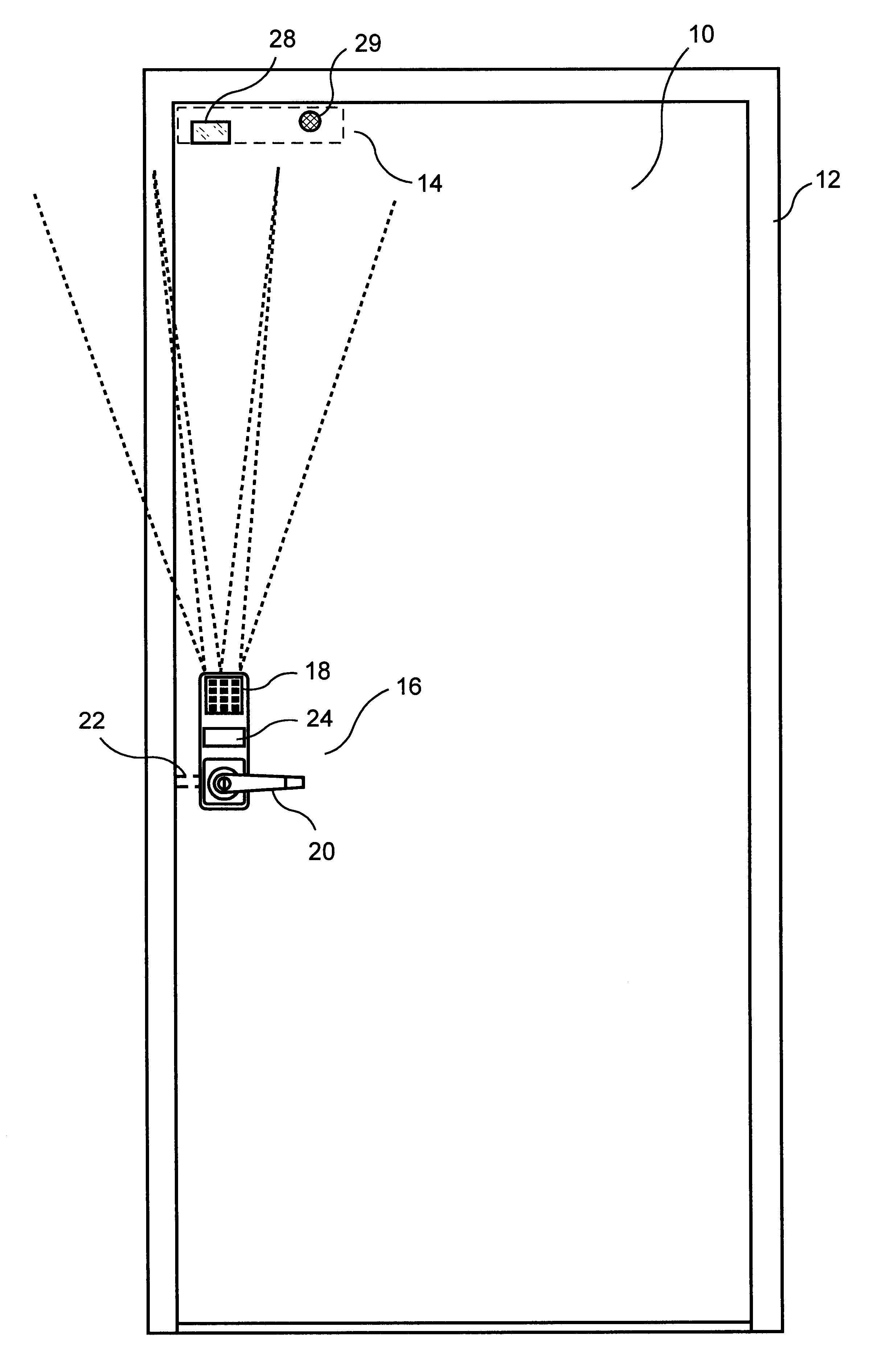
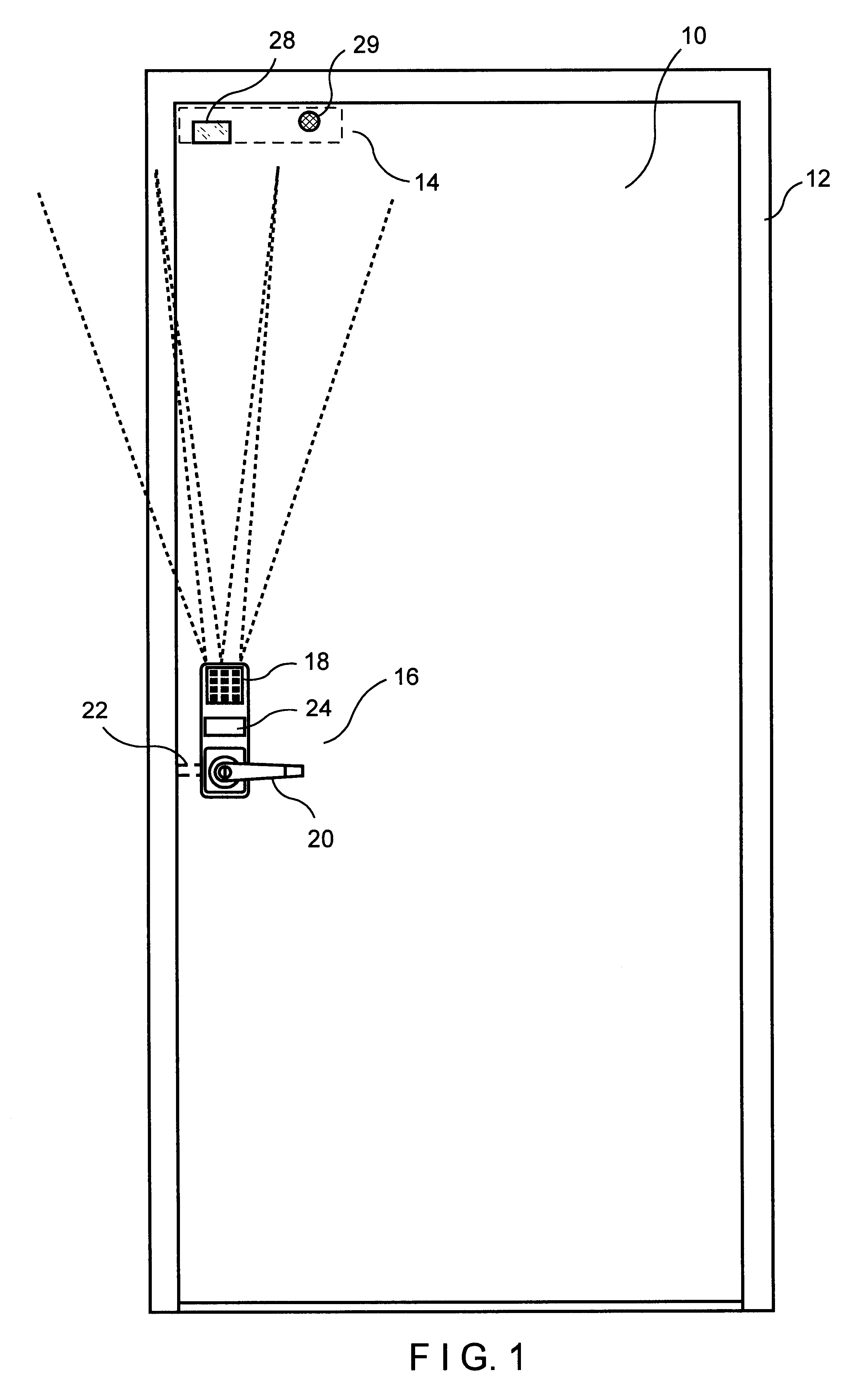
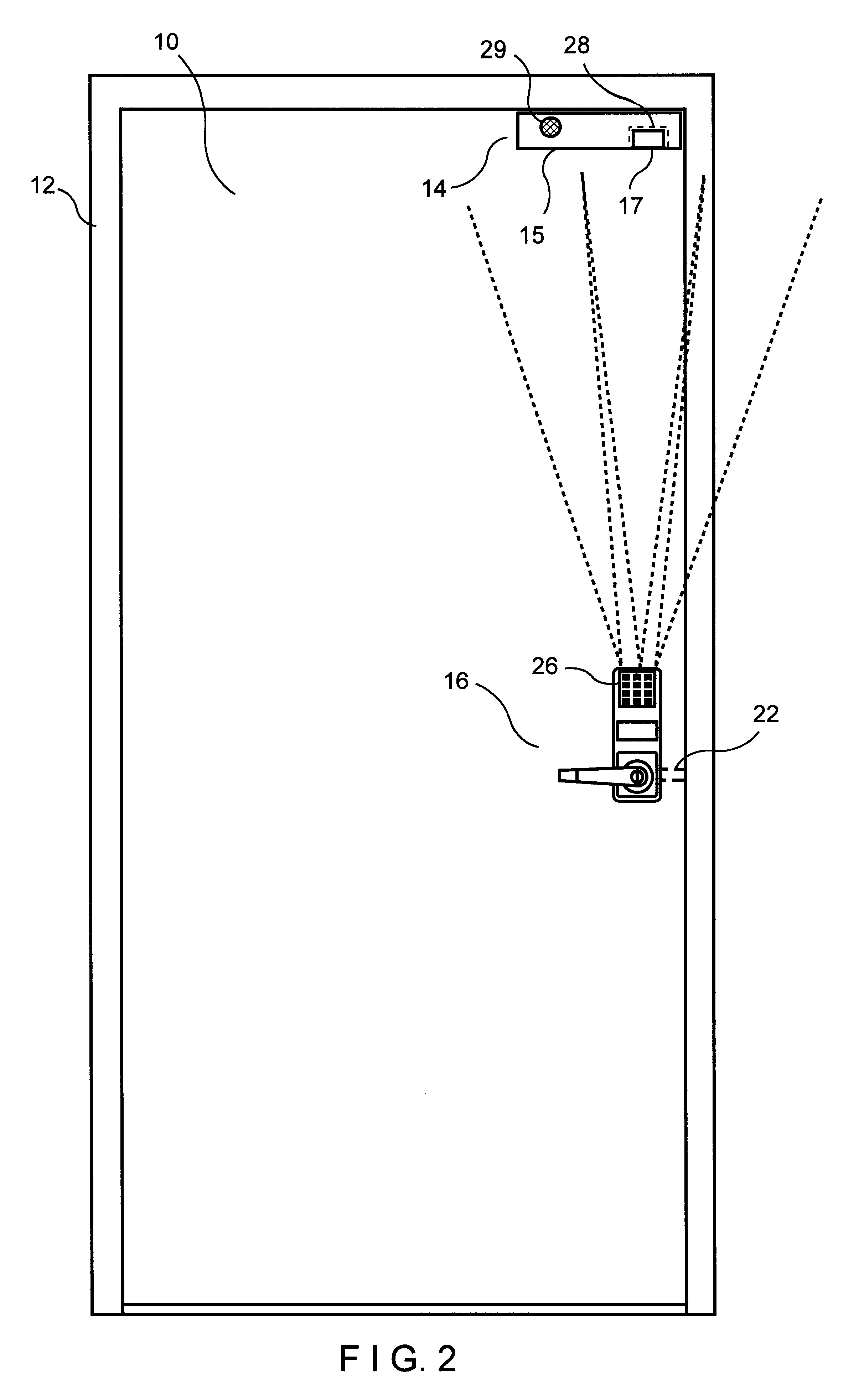
Both FIG. 1 and FIG. 2 include a door 10, a door frame 12, a magnetic lock assembly 14, and a controlled deadlatch assembly 16. FIG. 1 represents the outside of door 10 whereas FIG. 2 represents the inside of door 10. Magnetic lock assembly 14 is shown in shadow in FIG. 1 since it is preferred in most applications to have magnetic lock assembly 14 installed on the inside (or secured side) of door 10 for security purposes. However, magnetic lock assembly 14 obviously can be attached to either side of door 10 and door frame 12.

Controlled deadlatch assembly 16, as depicted in FIG. 1 and FIG. 2, actually is a combination input control device and deadlatch / door handle apparatus. In the embodiment shown, a keypad 18 is incorporated as the input control device. If an acceptable combination is punched into keypad 18, a predetermined delay time will commence in which a user can turn a door handle 20 to release a deadlatch 22 and permit entry into the secured premises. Keypad 20 can be replac...


PUM


Abstract

A two-point locking system for providing controlled access through a doorway is described comprising a controlled deadlatch assembly and a magnetic lock assembly. The controlled deadlatch assembly comprises (i) a deadlatch for selectively latching and unlatching a door, (ii) an input control device for selectively controlling the deadlatch, and (iii) a first wireless transmitter for transmitting a magnetic lock control signal. The magnetic lock assembly comprises (i) a metal housing unit, (ii) an armature plate, (iii) an electromagnetic element coupled to the housing unit and aligned to magnetically engage with the armature plate when selectively electrically energized, and (iv) a wireless receiver capable of receiving the magnetic lock control signal from the wireless transmitter. The magnetic lock control signal will typically disengage the magnetic lock assembly when the controlled deadlatch assembly is unlatched (thus unlocking the door and allowing access) and engage the magnetic lock assembly when the controlled deadlatch assembly is latched (thus locking the door and not allowing access). A second wireless transmitter can also be added to the magnetic lock assembly to communicate to a second wireless receiver at the controlled deadlatch assembly to provide two-way wireless communication between the two locking points.

Description

FIELD OF THE INVENTIONThis invention is generally directed to an access door locking system including a magnetic lock. More specifically, the access system of the present invention utilizes a two-point locking system integrating a deadlatch and a magnetic lock in a manner requiring no wiring between the controlled deadlatch assembly (typically located by the door handle) and the magnetic lock assembly (typically incorporated along the top of a door frame).BACKGROUND OF THE INVENTIONThere exists in the prior art a myriad of deadlatches and magnetic locks in the prior art to control ingress and egress through a door. Additionally, there are numerous integrated or so called two-point systems which incorporate both a controlled deadlatch assembly and a magnetic lock assembly. One common example is a controlled deadlatch activated by a panic bar which not only will release the deadlatch but also send an electrical signal through wiring that will release a magnetic lock. In such an exampl...

Claims


Application Information

Patent Timeline
IPC IPC(8): E05C19/16E05C19/00E05B17/22E05B63/00E05B47/00E05B17/00E05B63/14G07C9/00
CPCE05C19/166E05B17/22E05B47/0012E05B63/143E05B2047/0071E05B2047/0094G07C2009/00785G07C2009/00833G07C2209/64Y10T292/11Y10T70/7107Y10T70/7079Y10T292/06Y10T292/1021
Inventor BUCCOLA, CHARLES S.
Owner ALARM LOCK SYST
Why Eureka
Try Eureka