
Detector for surface texture measuring instrument

a surface texture and measuring instrument technology, applied in the direction of instruments, mechanical roughness/irregularity measurements, measurement gauges, etc., can solve the problems of poor bearing durability, difficult to achieve micro-measuring pressure, and bearings that cannot sustain the plugging for

Inactive Publication Date: 2002-12-03
MITUTOYO CORP
View PDF4 Cites 22 Cited by
  • Summary
  • Abstract
  • Description
  • Claims
  • Application Information

AI Technical Summary

Benefits of technology

In the present invention, rotary torque can be decreased by using the ball bearing. Further, the stylus can be exchanged by widely supporting the shaft, thus minimizing hysteresis and enabling measurement with a low measuring force.
When the limit switch is used as the detecting switch, the structure of the detecting switch can be simplified.

Problems solved by technology

However, in the conventional arrangement, the micro measuring pressure has been difficult to achieve on account of measuring orientation in accordance with measuring condition and problems caused in exchanging the stylus arm.
Hei 11-248404 can work at the micro measuring pressure, since a force is applied between a pointed end of the pivot fixed to the arm member and the bearing hole of the bearing in plugging the stylus arm in and out, durability of the bearing is inferior.
Further, when a great plugging force is applied in exchanging the stylus arm, the bearing cannot sustain the plugging force, and an independent special mechanism is additionally required.
However, in both cases, since a straightness correction function has to be switched on and off and a surface roughness calculation and a surface profile calculation have to be switched in accordance with the presence of the skid, troublesome operation has been required and error is likely to occurr.
Further, in order to conduct recalculation after the data outputted by the detector is stored, it has been difficult to identify whether the data was obtained by the skid measurement or the skidless measurement.

Method used


Image

  • Detector for surface texture measuring instrument
  • Detector for surface texture measuring instrument
  • Detector for surface texture measuring instrument

Examples


Embodiment Construction

)

An embodiment of the present invention will be described below with reference to attached drawings.

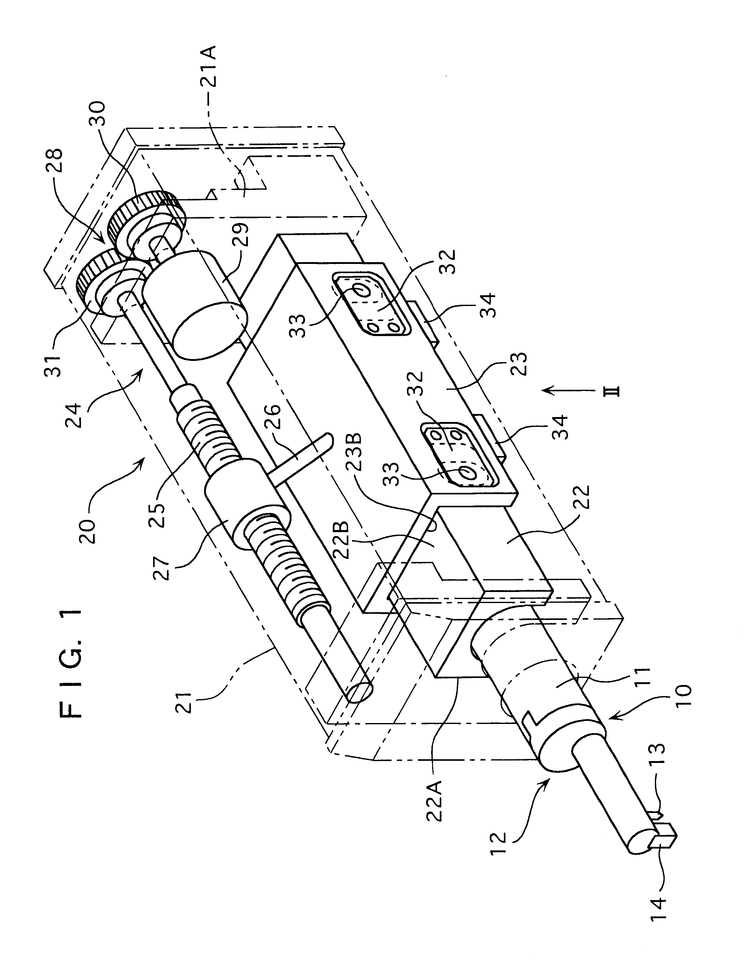
FIG. 1 is a summarized perspective view showing a surface texture measuring instrument embodying a detector according to an embodiment of the present invention.

In FIG. 1, the surface texture measuring instrument according to the present embodiment has a detector 10 for measuring a texture of a measurement surface of a workpiece and a drive unit 20 for advancing and retracting the detector 10 along the measurement surface.

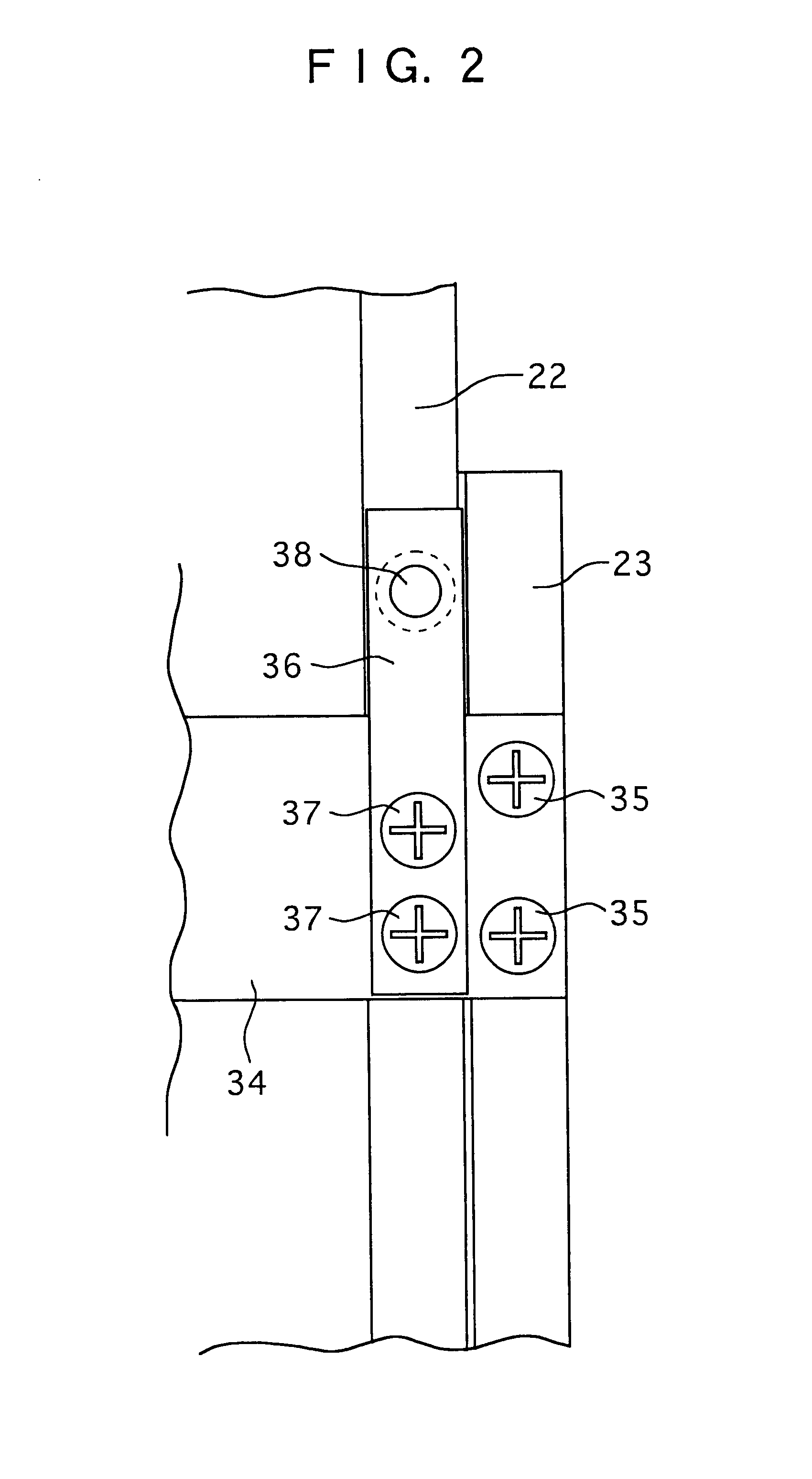
The drive unit 20 has a slider guide 22 having approximate bridge-type cross section fixed along longitudinal direction of a box-shaped casing 21, a slider 23 provided on the slider guide 22 slidable along the longitudinal direction and having the detector 10, and an advance-retraction mechanism 24 for advancing and retracting the slider 23 along the longitudinal direction.

The advance-retraction mechanism 24 has a feeding threaded shaft 25 disposed in the casing 21, a...


PUM


Abstract

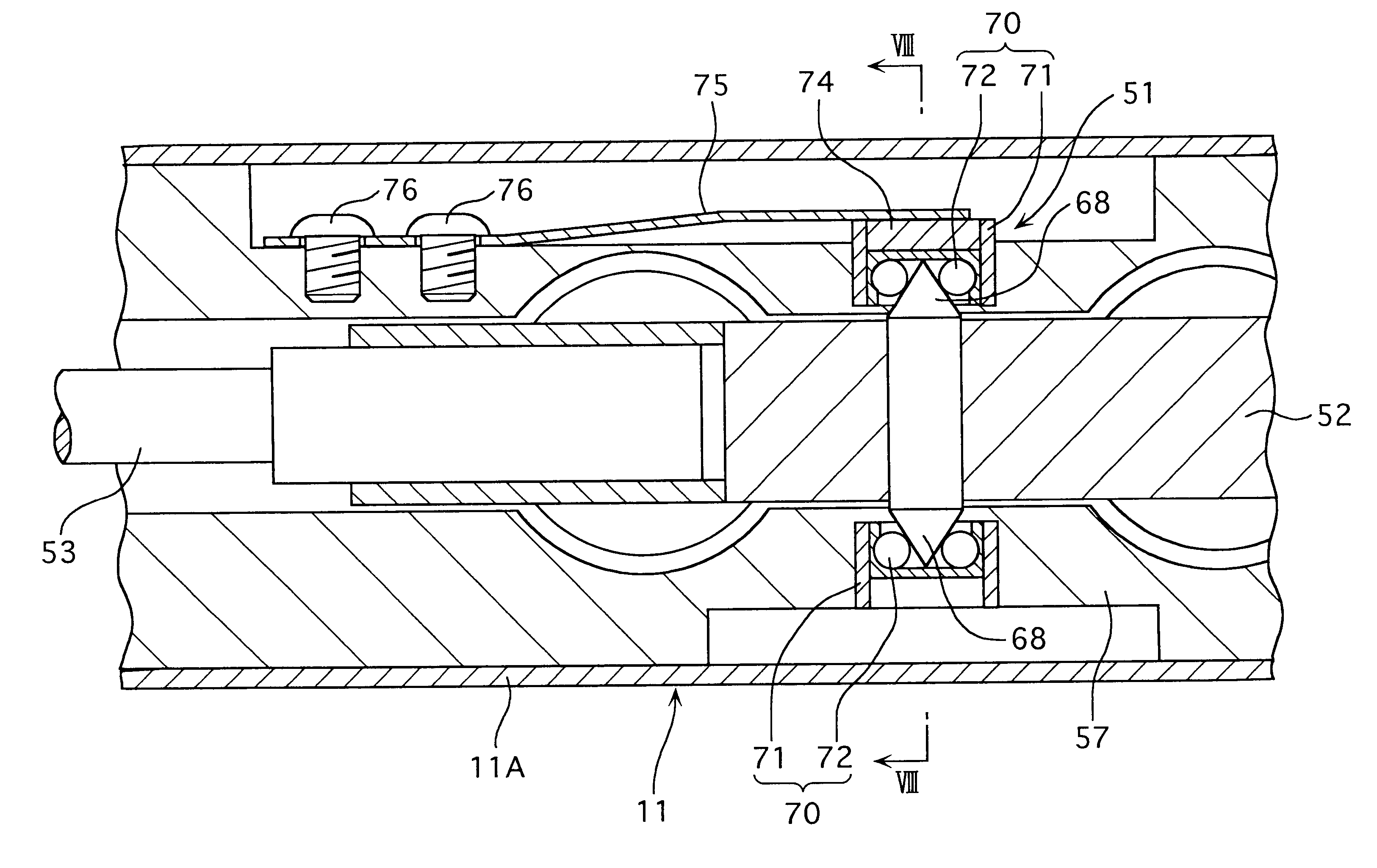
An arm member (52) detachably provided with a stylus arm (53) is rotatably held by a casing (11), where pivots (68) respectively project from both sides of a rotation center of the arm member (52), a first ball bearing (70) engaging with one of the pivots (68) is fixed to the casing (11) and a second ball bearing (70) engaging with the other one of the pivots (68) is fixed to the second ball bearing (70). A leaf-spring (75) has one end fixed to the casing (11) and the other end fixed to the second ball bearing (70). Since the second ball bearing (70) does not shift relative to the leaf-spring (75), measuring pressure remains stable.

Description

1. Field of the InventionThe present invention relates to a surface texture measuring instrument for measuring a surface roughness, waviness, and profile of a workpiece.2. Description of the Related ArtA surface texture measuring instrument has a detector having a stylus at a distal end thereof, the stylus being moved along a measurement surface to detect displacement of the stylus as a measurement data.The detector used in the surface texture measuring instrument has an elongated arm member rotatably attached inside an approximately cylindrical casing. A stylus arm having a stylus is provided at the distal end of the arm member. Displacement of the stylus is detected by a detecting unit provided to the arm member.Conventionally, in order to rotatably support the arm member inside the casing, a pivot has been fixed to a rotation center of the arm member and a bottomed cylindrical bearing for engaging a pointed end of the pivot in a bottom bearing hole is fixed to the casing (Japanes...

Claims


Application Information

Patent Timeline
IPC IPC(8): G01B3/22G01B5/28G01B21/30
CPCG01B3/22G01B5/28
Inventor FUJII, NOBUYOSHIIMAMURA, KOUICHI
Owner MITUTOYO CORP
Learn More