

Control valve for variable capacity compressor
a variable capacity compressor and control valve technology, which is applied in the direction of valve operating means/release devices, machines/engines, positive displacement liquid engines, etc., can solve the problems of increased hysteresis in the valve opening, difficult to obtain high straightness in the bellows, and poor control
- Summary
- Abstract
- Description
- Claims
- Application Information
AI Technical Summary
Benefits of technology
Problems solved by technology
Method used
Image

Examples
first embodiment
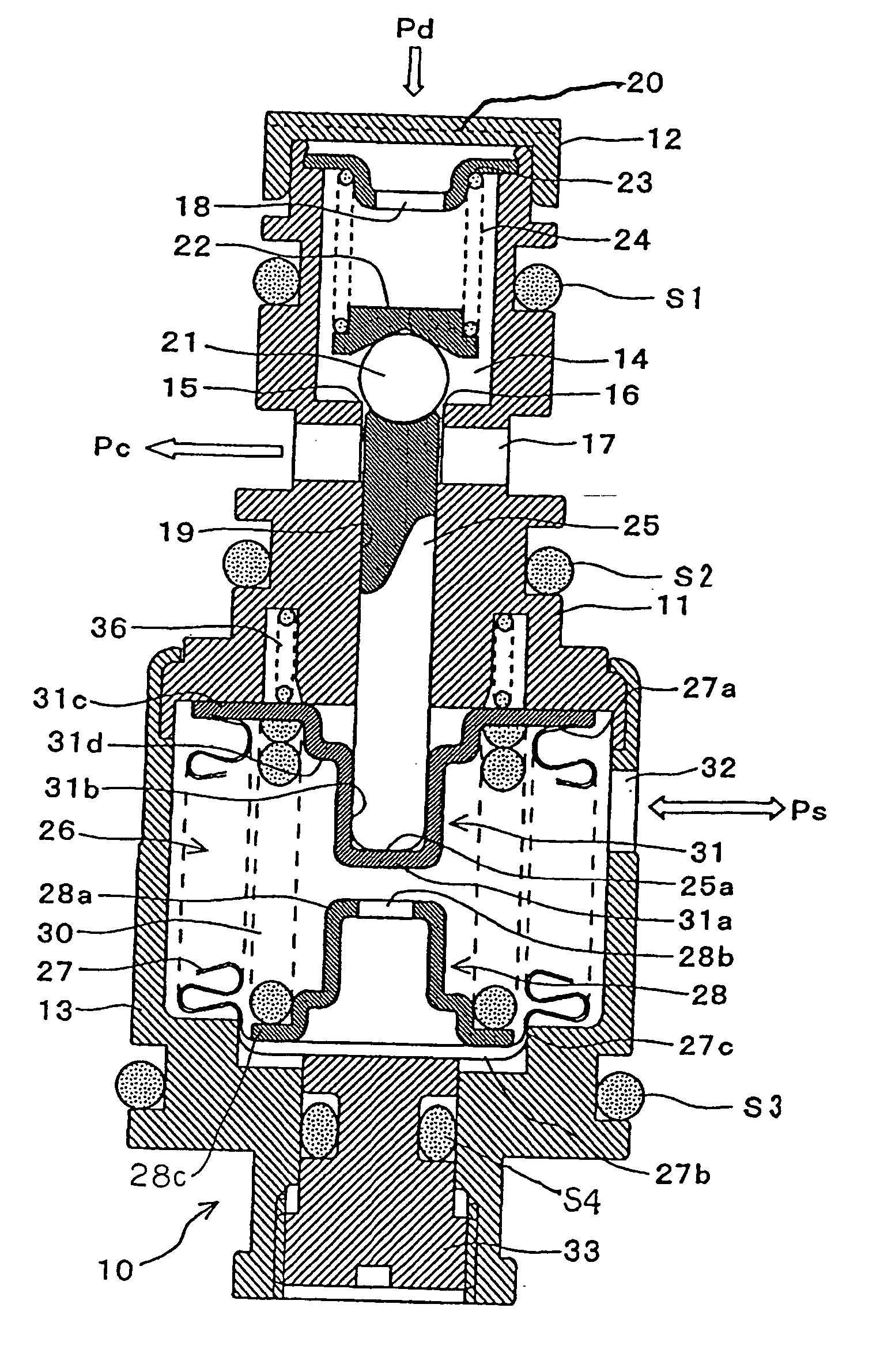
[0021] First, a control valve according to the present invention will be described by referring to FIG.
[0022] The control valve 10 shown in FIG. 1 is inserted and fixed into a control valve mounting hole formed in a housing of a variable capacity compressor (not shown) as a flow control valve for a flow rate of a refrigerant from a discharge pipe for the refrigerant to a crankcase.
[0023] The control valve 10 is formed of a tubular valve housing 11, an end cap 12 mounted to an upper end of the valve housing 11, and a bellows case 13 connected to a lower end of the valve housing 11 by caulking.
[0024] An assembly of the valve housing 11 and the end cap 12 is formed of a valve chest 14, a valve port 16 defined by a valve seat portion 15, a first port 17 formed on one side of the valve port 16, a spring receiving seat 23 disposed on the other side of the valve port 16 through the valve chest 14, a second port 18 formed in the spring receiving seat 23, and a valve rod retaining hole 19. T...
second embodiment
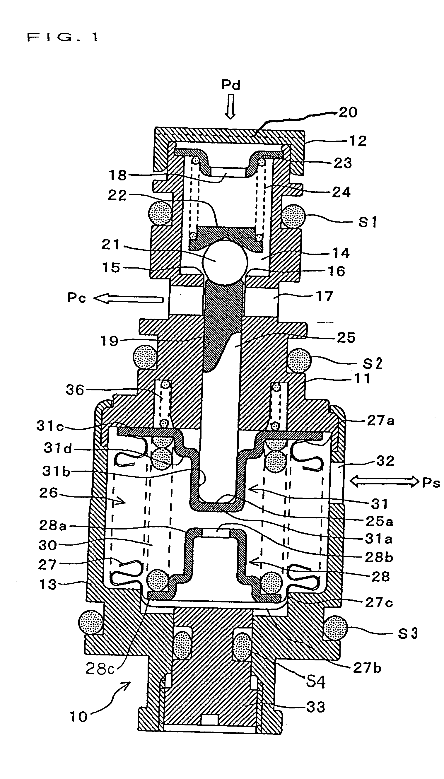
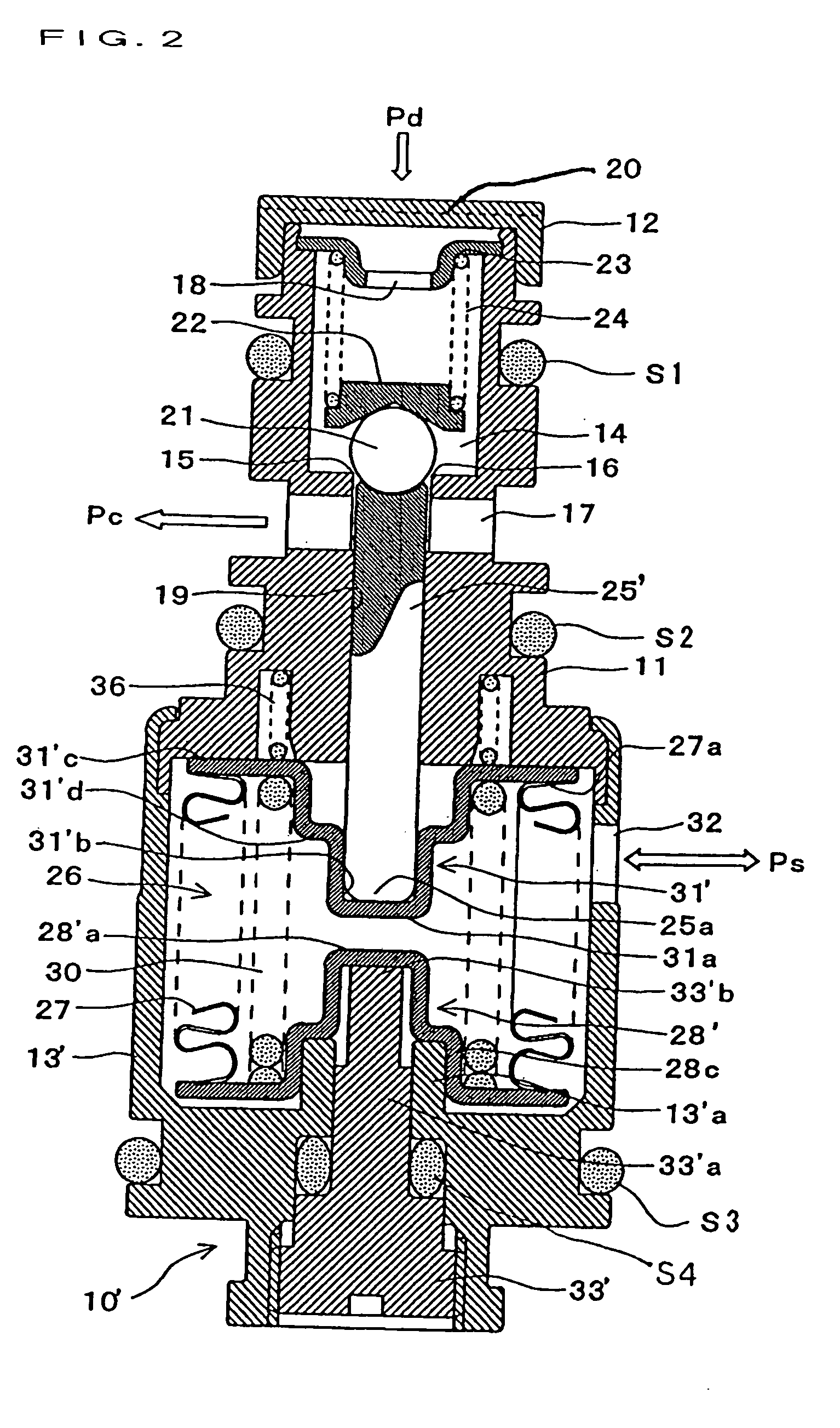
[0041] Next, a control valve according to the invention will be described by referring to FIG. 2. In FIG. 2, components similar to those shown in FIG. 1 (first embodiment) are denoted by similar reference numerals.
[0042] The control valve 10' of the embodiment is different from the control valve 10 of the first embodiment in (1) a shape of a patch member 31' and (2) shapes of a bellows case 13', a lower patch member 28', and an adjusting screw member 33' for supporting the lower patch member 28'.
[0043] With regard to the above difference (1), in the present embodiment, a large-diameter portion 31'd formed in a midway position between the base portion 31'c and a fitting recessed portion 31'b of the patch member 31' is formed to be deeper than the large-diameter portion 31d in the first embodiment. By an amount by which the large-diameter portion 31'd is made deeper, the fitting recessed portion 31'b of the patch member 31' is made shallower. Therefore, a length of a portion of the va...
third embodiment
[0048] Next, a control valve according to the invention will be described by referring to FIG. 3. In FIG. 3, components similar to those shown in FIG. 1 (first embodiment) are denoted by similar reference numerals.
[0049] Similarly to the control valve 10 in FIG. 1 (first embodiment), the control valve 10" shown in FIG. 3 includes as a pressure sensing element the bellows main body 27 retained in the bellows case 13 with an airtight structure and expansion and contraction of the bellows main body 27 in response to variations in the inlet pressure Ps of the variable capacity compressor are transferred to the ball valve 21 through the valve rod 25" supported in the valve rod retaining hole 19 formed in the valve housing 11 integral with the bellows case 13 to thereby change the valve opening degree.
[0050] The control valve 10 is similar to the above-described first embodiment in that (1) the patch member 31 is provided to the movable-side end portion of the bellows main body 27 and the...
PUM
 Abstract
Description
Claims
Application Information