Continuum manipulator

a technology of manipulator and bending plate, which is applied in the field of continuous manipulator, can solve the problems of reducing limiting the freedom of conventional catheters, so as to improve the repeatability of bending, prevent unwanted twisting of the tip of the stack, and reduce the effect of hysteresis

Inactive Publication Date: 2017-06-13
KINGS COLLEGE LONDON
View PDF24 Cites 3 Cited by
  • Summary
  • Abstract
  • Description
  • Claims
  • Application Information

AI Technical Summary

Benefits of technology

[0006]Embodiments of the present invention provide a continuum manipulator that can be used, for example, as a steerable catheter tip. The manipulator of the embodiments comprises a plurality of segments arranged in a stack, which is then able to bend in a range of directions away from the long axis of the stack. In one embodiment the segments include a helical portion which winds in the direction of the long axis of the stack, and can thus bend away from the long axis in any direction. In another embodiment the segments include a backbone portion with cantilevered rings extending from the backbone portion, separated by bending gaps which allow the segment to bend in a range of directions away from the backbone portion so that the bending gap between the rings closes. In some embodiments an elastomeric rod such as, for example, a carbon fibre rod is included as a backbone for the stack, to minimise hysteresis and improve repeatability of bending. In addition, in embodiments of the invention tendon control channels are provided formed within the segments, through which tendon control wires extend to apply compression and / or bending forces to the stack. Having the control channels formed internally to the stack strengthens the stack and makes the stacked structure conform to the channel(s). In particular unwanted twisting of the tip of the stack can be prevented.
[0007]In view of the above, from one aspect there is provided a continuum manipulator comprising a plurality of segments arranged in a stack, the segments being deformable in a range of directions away from the long axis of the stack to allow the stack to bend in the range of directions away from the long axis thereof. The segments may further comprise a backbone channel running through each segment parallel to the long axis thereof and may be arranged in the stack with the respective backbone channels in alignment. An elastomeric rod may then be inserted into and run through the backbone channels of the segments. This provides significant advantages in allowing the stack to return to its original position after bending, and also to assume the same bent position for the same tendon displacement. That is, repeatability of bending is improved, and hysteresis in forwards and reverse bending is reduced.

Problems solved by technology

The main advantages of using catheters are the reduced trauma and shorter recovery time for the patient, but conventional catheters usually have limited degrees of freedom, as the catheter can typically only rotate and slide through the trocar port.
However, this technique returns only 2D images with poor soft tissue contrast.

Method used


Image

  • Continuum manipulator
  • Continuum manipulator
  • Continuum manipulator

Examples


first embodiment

[0039]the present invention will now be described with respect to FIGS. 1 to 7.

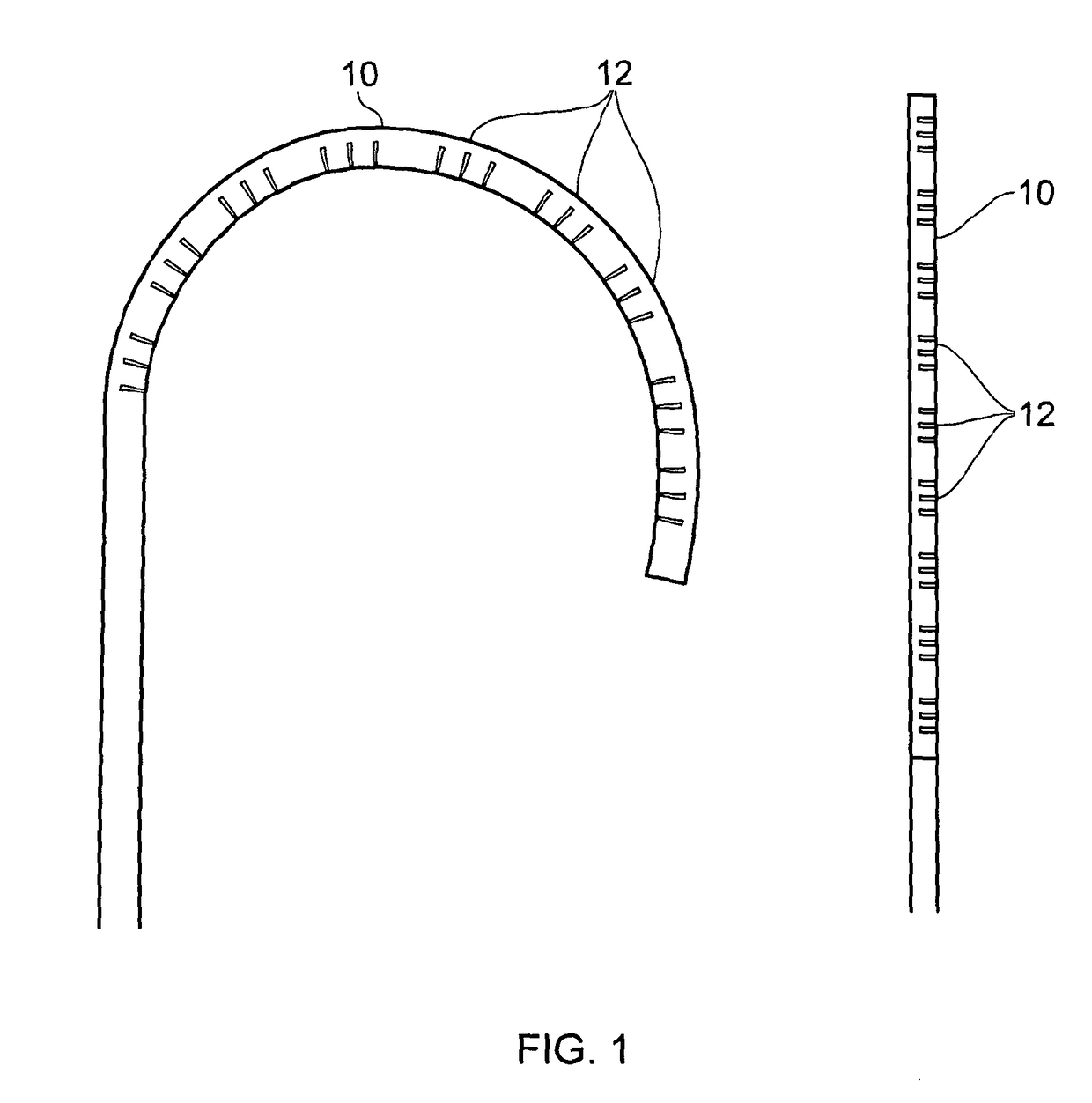
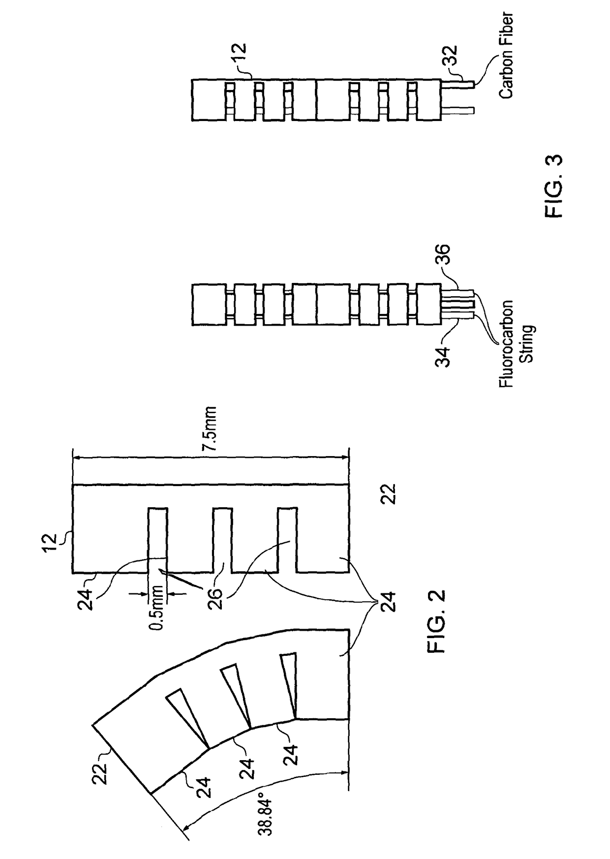
[0040]The first embodiment of the present invention provides a continuum manipulator in the form of a steerable catheter tip 10, as shown in FIG. 1. The steerable catheter tip 10 is shown in the left hand photograph of FIG. 1 in a bent configuration, and in the right hand photograph in an unbent configuration. The steerable catheter tip 10 is formed from nine individual and interconnecting segments 12, which are effectively stacked one on top of the other along the long axis of the catheter tip to form a continuum structure. The number of segments may vary depending on application to enlarge or shorten the steerable length. Each segment 12 contains integral tendon channels through which steering or guide tendons of the catheter pass, as well as a backbone channel for a carbon fibre backbone, as will be described later. In operation, the steering tendons can be manipulated either by hand, or by robot, to c...

second embodiment

[0051]the invention will now be described with respect to FIGS. 8 to 11.

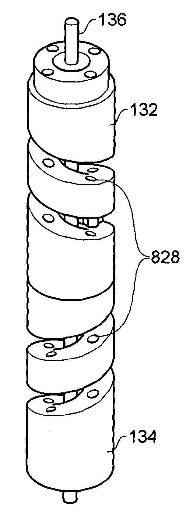
[0052]FIG. 8 shows two photographs of a continuum manipulator in the form of a steerable catheter tip according to the second embodiment of the invention. In particular, the catheter tip 80 is again formed from individual stacked segments 82, as shown in more detail in FIG. 9. The individual stacked segments 82 stack one on top of each other using a male and female mating arrangement, and the catheter tip can bend in any direction from the straight position shown in the photograph on the left hand side of FIG. 8, to a bent configuration shown in the photograph on the right hand side of FIG. 8.

[0053]As mentioned, FIG. 9 shows respectively top and bottom perspective views of a segment 82 of the catheter tip 80. Each segment 82 is generally cylindrical in shape, but arranged in a helical configuration. In particular, each segment 82 is arranged as a hollow cylinder with a lumen channel 830 running along the centre ...


PUM


Abstract

Embodiments of the present invention provide a continuum manipulator that can be used, for example, as a steerable catheter tip. The manipulator of the embodiments comprises a plurality of segments arranged in a stack, which is then able to bend in a range of directions away from the long axis of the stack. In one embodiment the segments include a helical portion which winds in the direction of the long axis of the stack, and can thus bend away from the long axis in any direction. In some embodiments a carbon fiber rod is included as a backbone for the stack, to minimize hysteresis and improve repeatability of bending. In addition, in embodiments of the invention tendon control channels are provided formed within the segments, through which tendon control wires extend to apply compression and / or bending forces to the stack.

Description

CROSS-REFERENCE TO RELATED APPLICATIONS[0001]This application is a nation stage entry under 35 U.S.C. section 371 of PCT Application Serial No. PCT / GB2012 / 051860, filed on 1 Aug. 2012 and published as WO 2013 / 017875 on 7 Feb. 2013, which claims priority to GB provisional documents 1113534.0, 1113532.4, 1113536.5 all filed on 4 Aug. 2011.TECHNICAL FIELD[0002]The present invention relates to a continuum manipulator, and in one embodiment a continuum manipulator that is suitable for use as a steerable catheter tip usable in, for example, cardiac catheterisation procedures, endoscopic imaging, and medicine delivery, amongst other uses.BACKGROUND TO THE INVENTION AND PRIOR ART[0003]Cardiac catheterisation is a minimally invasive surgery (MIS) procedure performed using flexible, thin and long tubes called catheters. The catheter is inserted through a small incision into the femoral vein which leads to the heart, and the goal is usually to reach specific locations inside the body (e.g. the...

Claims


Application Information

Patent Timeline
Patent Type & Authority Patents(United States)
IPC IPC(8): A61B1/00A61B1/005A61M25/01A61B1/313
CPCA61M25/0138A61B1/0056A61B1/0057A61B1/00073A61B1/3132A61M25/0147
Inventor ATAOLLAHI, ASGHARALTHOEFER, KASPARSCHAEFFTER, TOBIAS RICHARDRHODE, KAWALDEEP
Owner KINGS COLLEGE LONDON
Why Eureka
Try Eureka