

Positioning system for an observation device using a tensioned filament and locator ball
- Summary
- Abstract
- Description
- Claims
- Application Information
AI Technical Summary
Benefits of technology
Problems solved by technology
Method used
Image


Examples
Embodiment Construction
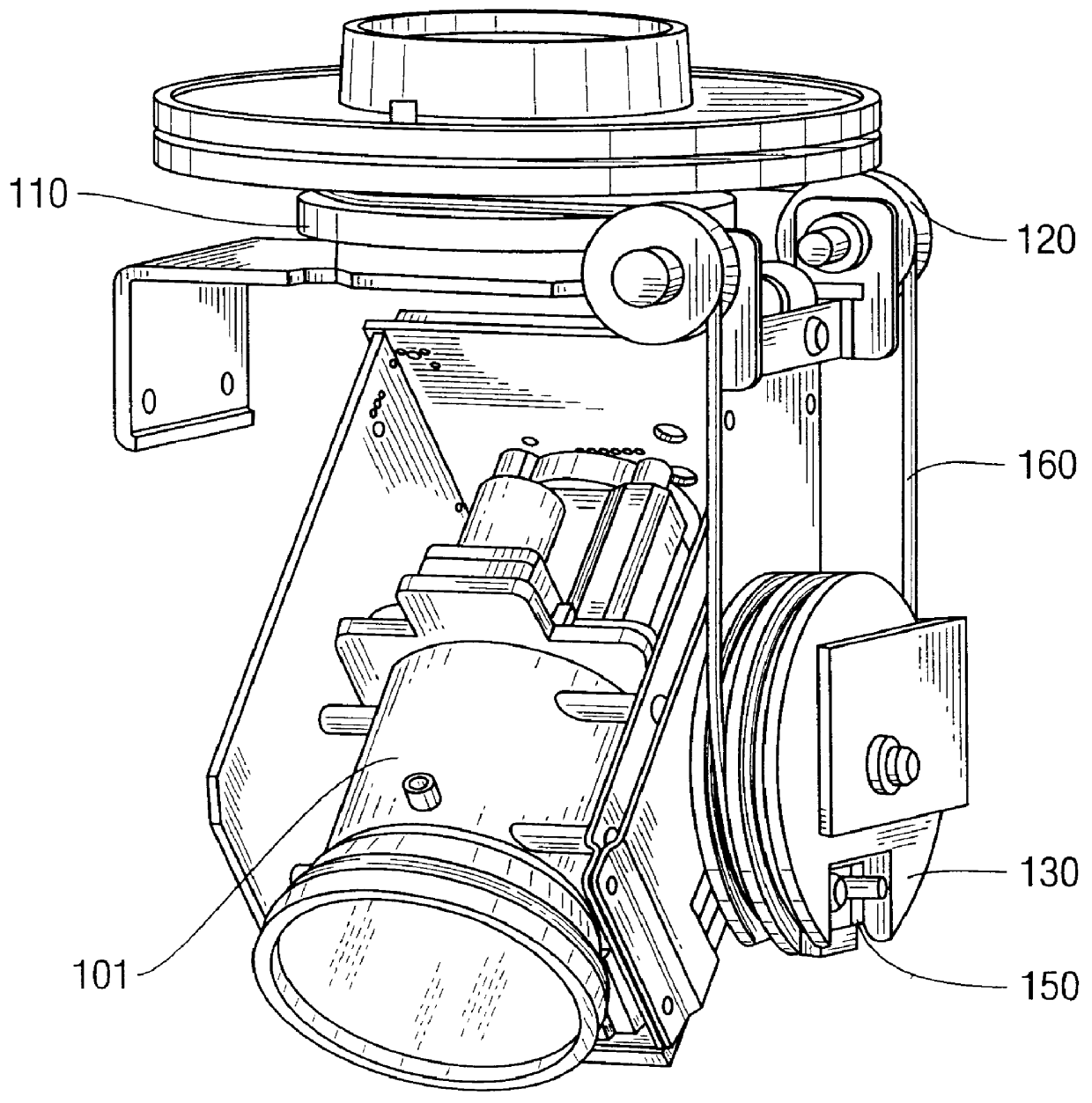
FIGS. 1A and 1B shows a cable drive for a Pan / Tilt / Zoom camera. A motor, not shown, effects the rotation of the driving pulley 110. If cable 160 is properly tensioned, a rotation of the driving pulley 110 causes a movement of the cable 160. The driven pulley 130 is rotated by the action of the movement of the cable 160. The idler wheels 120 allow for a change of direction of the cable, thereby allowing a rotation of the driving pulley about a vertical axis to be converted to a rotation of the driven pulley about a horizontal axis. As shown, this cable and pulley arrangement produces a tilt of a camera 101, which is axially attached to the driven pulley 130, in direct relationship to the rotation of the driving pulley.
Traditionally, the camera 101 is adjusted while the adjuster is viewing the scene within the camera's field of view. The motor which drives the driven pulley is energized to rotate in one direction or the other until the desired scene comes into view. In such a system, ...
PUM
 Abstract
Description
Claims
Application Information