Piping joint and integrated valve with it

a technology of piping joints and valves, applied in the direction of adjustable joints, fluid pressure sealing joints, sleeves/socket joints, etc., can solve the problems of inferior construction, high inferiority rate, and low precision of fine manufacturing of products, and achieve the effect of easing maintenan

Inactive Publication Date: 2002-12-03
JAE YOUNG SHIM
View PDF15 Cites 51 Cited by
  • Summary
  • Abstract
  • Description
  • Claims
  • Application Information

AI Technical Summary

Benefits of technology

The purpose of the invention designed to solve problems of said prior art is to provide a piping joint and a valve controlling fluid flow, in which simple joint tools can conjoin pipes without screws or extra flange coupling processes, in piping for heating, water service, hygiene, and industry. With the invention, first, pipe's watertightness is improved, second, connection can be maintained firm, third, tightening level can be detected from the outside so that a proper level can be obtained, and fourth, possible repeated use ease its maintenance.

Problems solved by technology

First, to form tapered screw part 13a around the inside of the pipe-connecting part 13 results in difficulties in fine manufacturing and low precision of products.
Thus, increased errors in manufacturing result in high inferiority rate in products and piping using this product may result in inferior construction Second, the screw part 13a is formed inside said pipe-connecting part 13 through whole length and the first packing ring 16 and the second packing ring are inserted into screw part 13a.
Therefore, it is inconvenient for maintenance because it is difficult to take them apart when repair needed.
Third, in adjusting the proper tightening power to the bush 20, it is hard to detect required certain level of tightening power from outside.
This results in disadvantages that, when tightening power is too strong, damage(s) can occur on the first packing ring 16, the second packing ring 18, screw part 13a in pipe-connecting part 13, and screw part 20a in the bush 20 and, when tightening power is weak, sealing condition gets bad.

Method used


Image

  • Piping joint and integrated valve with it
  • Piping joint and integrated valve with it
  • Piping joint and integrated valve with it

Examples


first embodiment

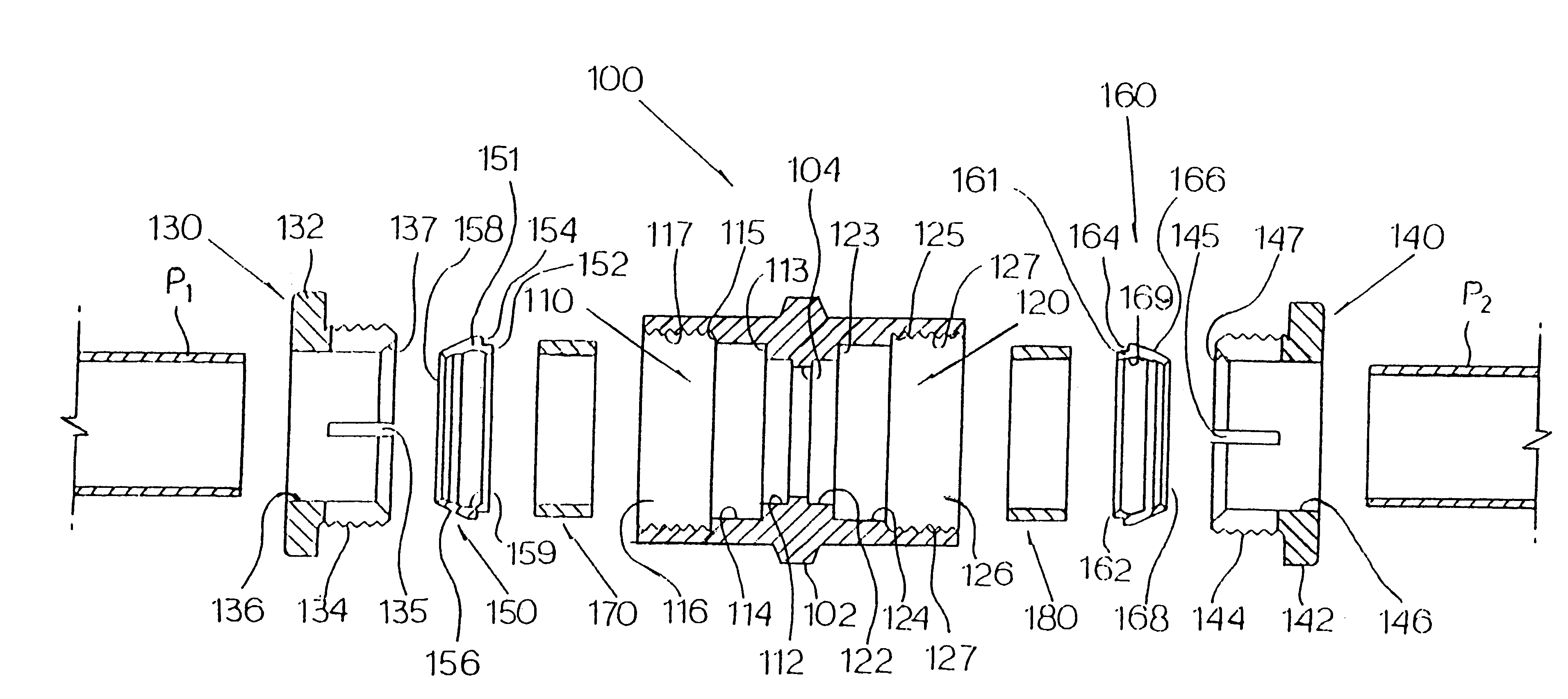
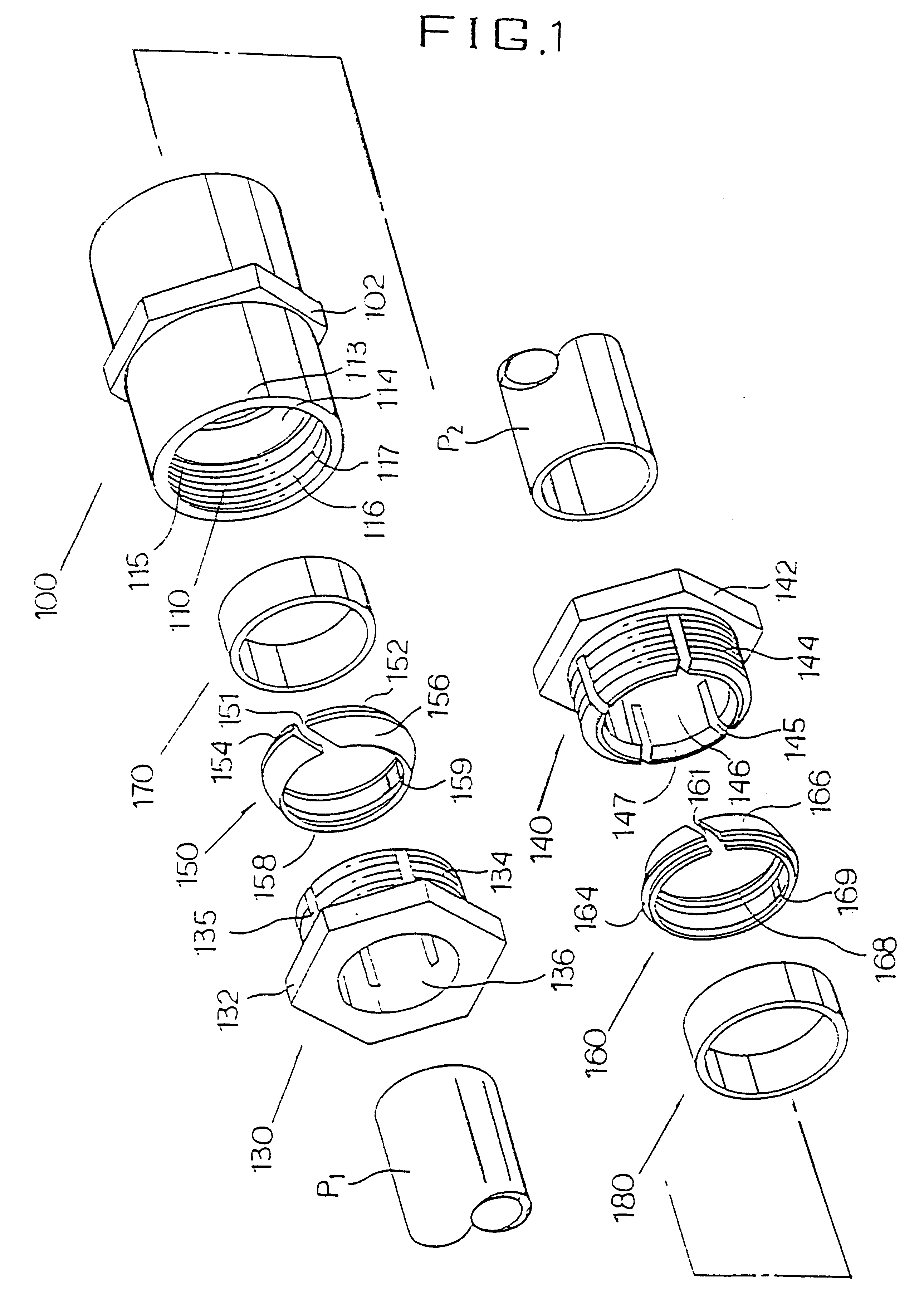
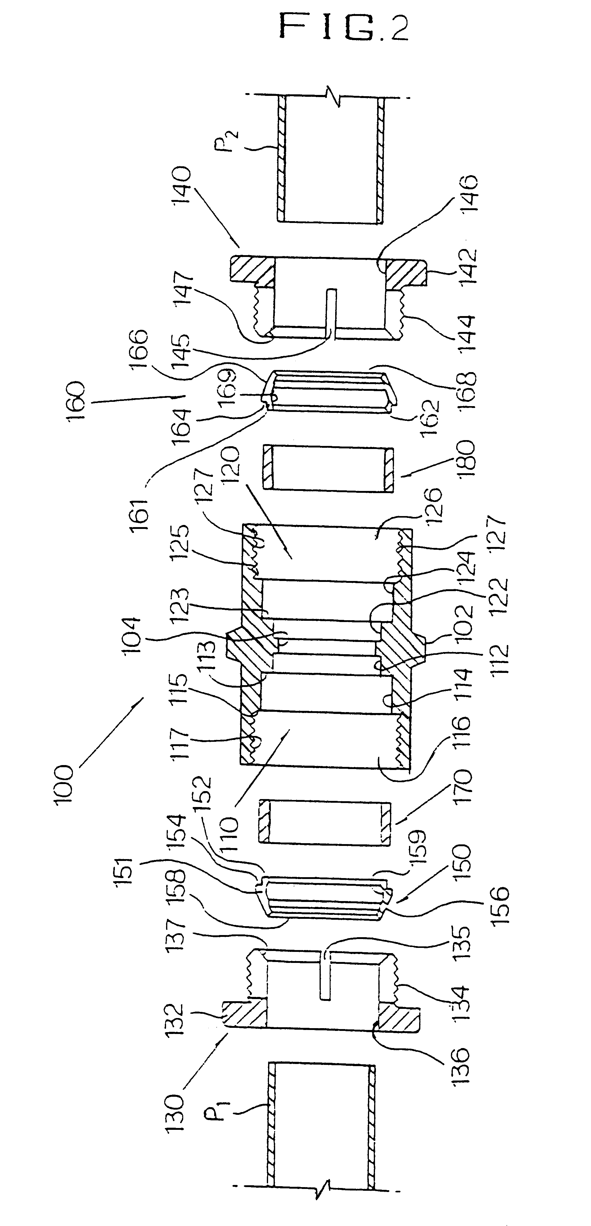
The process combining two pipes in series using an union joint of the invention is described below. First, bushes 130, 140 and the second packing rings 150, 160 are put in pipes P1, P2 in order, and the first packing rings 170, 180 are inserted into the edges of the pipes P1, P2.

Then, a union joint body is placed between the pipes P1, P2 and pipes P1, P2 are inserted into the connecting parts 110, 120 on both sides of the joint body then, the first packing rings 170, 180 on the ends of the pipes P1, P2 are inserted into the first holes 112, 129 placed inside of the each connecting parts 110, 120.

At this point, when bushes 130, 140 are rotated holding the joint body 100 not to rotate, male threads 134, 144 of bushes 130, 140 are screwed at connecting parts 110, 120 and inserted inward. At the same time, the second packing rings 150, 160 inserted before bushes 130, 140 are placed inside of the third holes 116, 126 of the connecting parts 110, 120. The first packing rings 170, 180 at t...

sixth embodiment

The sixth embodiment described in FIG. 9 is a T joint which have three connecting parts 510, 520, 530 to conjoin three same sized pipes P1, P1, P3 into one joint body 500.

seventh embodiment

The seventh embodiment described in FIG. 10 is a transformation of said first embodiment This joint have two different sized connecting parts 610, 620 on both sides of the joint body to connect two different sized pipes P1, P2 in series.

Transformed embodiment of the sixth embodiment described in FIG. 11 is T joint. Connecting parts 710, 770 are formed on both sides of the joint body 700, and contact part 730 with a female thread 732 is formed in the middle, and materials other than pipes are screwed directly into the contact part 730 as shown in the third embodiment. Another transformed embodiment of the sixth embodiment described in FIG. FIG. 12 is T joint. Identical sized connecting parts 810, 820 are formed on both sides of the joint and the connecting parts 810, 820 make a right angle with a middle connecting part 830 which is formed in different size, so a pipe with a narrower diameter can branch off. FIG. 13 and 14 describes a valve, as same as shown in second embodiment and t...


PUM


Abstract

The present invention provides a piping joint and integrated valve with the piping joint, which improve airtight and watertight, maintain connection firm, and keep constant quality regardless repeated user. In connecting part (110, 120) of the joint body (100), the first holes (112, 113), the second packing holes (114, 124) where the first packing rings (170, 180) are inserted, the third holes (116, 126) with a female threaded part inside conjoining the second packing rings (150, 160) and bushes (130, 140), having three holes formed three phases outward on the concentric circle. The first packing rings (170, 180) are made of silicon or Teflon(R) that is flexible and sustainable against heat. One side of said second packing rings (150, 160) contact the first packing rings (170, 180), and ground the contact parts (152, 162) stoppers (154, 164) are placed to prevent the second packing rings (150, 160) from inserting too deeply into inside of the connecting parts (110, 120) of the joint body (100) and the other sides are tapered down in a certain angle to contact the slant (137, 147) of edges or bushes (130, 140), and the tapered parts (156, 166) are equipped with projections (158, 168) inside to hold pipes (P1, P2) firm.

Description

TECHNICAL FIELD AND BACKGROUND ARTThe present invention is a piping joint and an integrated valve with it. The invention improves watertightness of connecting parts, maintains the joint firm and keeps its quality regardless repeated uses, thus it is convenient for maintenance.Prior art related to the present invention is "Valve with a pipe-connecting part" published in Korean Utility Model Specification No. 97-1671. Said prior art was invented by the current inventor and its technical gist is that, as shown in FIGS. 16 and 18, a valve consists of a ball 11 operated by a lever 17 to pass through or to block an entrance and an exit of the valve, tapered screw part 13a equipped along circumferential side inside of pipe-connecting part 13 in said valve, screw part 20a formed on circumferential side to correspond to said screw part 13a, an open hole 20b through its axis, a bush 20 with a slant 20d on its longitudinal section, the first packing ring 16 with a slant 16b on the side; the se...

Claims


Application Information

Patent Timeline
Patent Type & Authority Patents(United States)
IPC IPC(8): F16L19/00F16L19/06F16L19/08
CPCF16L19/061F16L19/086F16L19/075F16L19/08
Inventor SHIM, JAE YOUNG
Owner JAE YOUNG SHIM
Why Eureka
Try Eureka