

Electrical circuit board and method for making the same
a technology of electrical circuit board and circuit board, which is applied in the direction of insulated conductors, power cables, cables, etc., can solve the problems of irrevocably damage or destroy these components, substantial amounts of heat produced and/or generated, and is typically made and/or manufactured from additional components
- Summary
- Abstract
- Description
- Claims
- Application Information
AI Technical Summary
Benefits of technology
Problems solved by technology
Method used
Image

Examples
second embodiment
Referring now to FIG. 2, there is shown a partial sectional view of two portions 132, 134 of a multi-layer circuit board 130 which is formed according to the present invention. Circuit board 130 includes multiple heat pipes or channels 136, 138, 140, 142 which are formed within the layers of circuit board 130 in a manner substantially identical to that used to form pipe 78. Circuit board 130 includes a core member 162 which is substantially identical to core member 62, adhesive layers 164, 166 which are substantially identical to layers 64, 66, conductive members 168, 170 which are substantially and respectively identical to members 18, 20, and aluminum layers 172, which are substantially identical to layers 16. In the preferred embodiment of the invention, channels 136, 138, 140 and 142 are all interconnected. In other alternate embodiments, channels 136-142 may each be independent, or may each be interconnected with only certain other channels. In the preferred embodiment of the i...
third embodiment
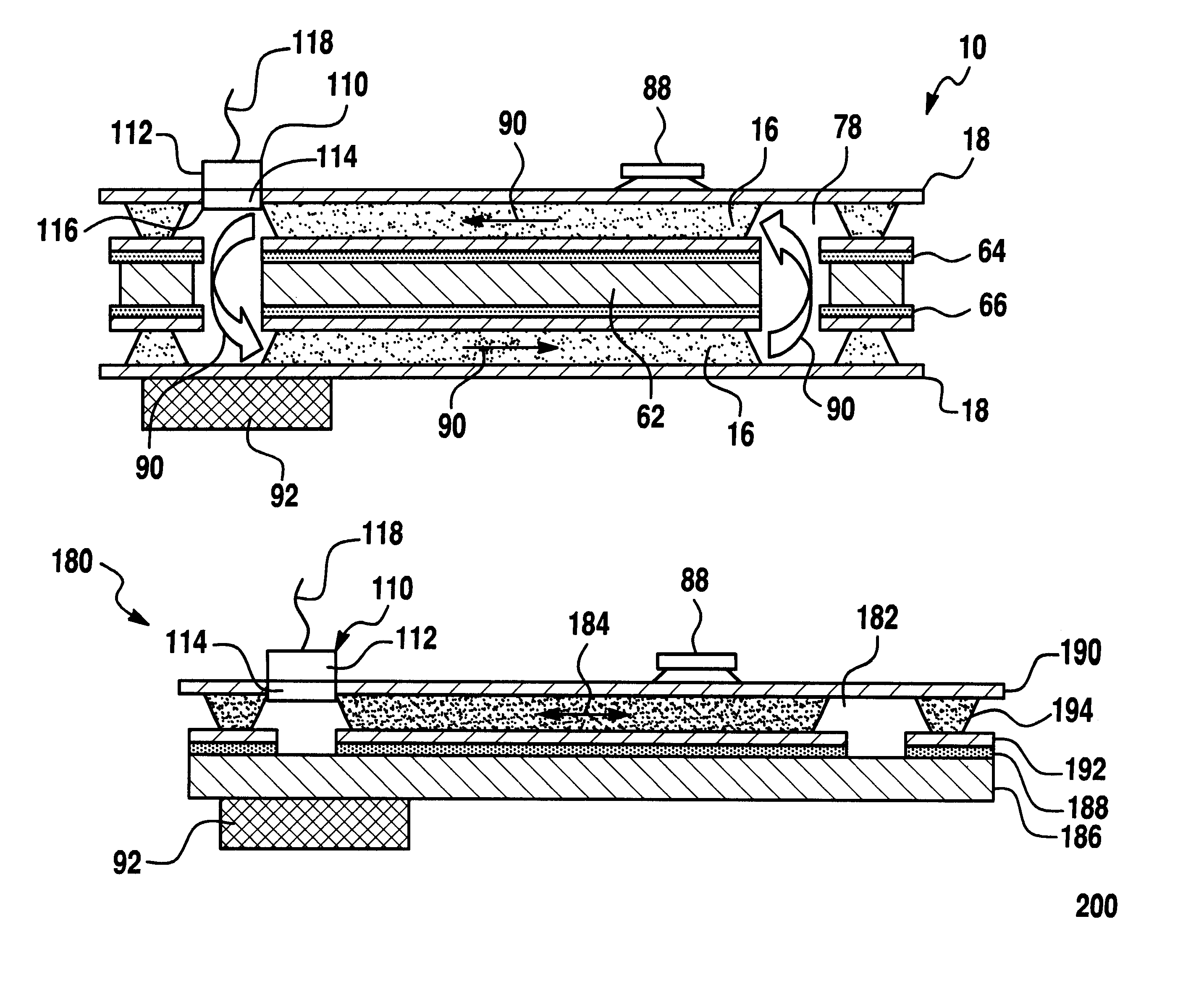
Referring now to FIG. 3, there is shown a circuit board 180 which is formed in accordance with the teachings of the present invention. As shown in FIG. 3, circuit board 180 includes a heat pipe 182 which is formed (e.g., etched) within a single layer (e.g., layer 194) of circuit board 180 and comprises a single channel or passage. Circuit board 180 includes a core member 186 which is substantially identical to core member 62, an adhesive layer 188 which is substantially identical to layer 64, conductive member 190, 192 which are substantially and respectively identical to members 18, 20, and aluminum layer 194 which is substantially identical to layer 16.
Circuit board 180 includes a heat pump 110 and a hot power device 88. Channel 182 includes or contains a cooling fluid, vapor and / or gas, and heat pump 110 functions in a manner substantially identical to heat pump 110 of circuit board 10. That is, when activated, pump 110 effectively circulates fluid within channel 182 (e.g., in th...
fourth embodiment
Referring now to FIG. 4, there is shown a circuit board 200 which is formed in accordance with the teachings of the present invention. Circuit board 200 is substantially similar to circuit board 180 with the exception that multiple channels or pipes 202, 204, 206, 208 and 210 are formed within layer 194 and are effective to transfer cooling fluid, vapor and / or gas through circuit board 200 in the directions of arrows 212. Additionally, circuit board 200 includes a pair of heat sinks 92 and a pair of heat pumps 110 which function in a manner substantially identical to heat pump 110 of circuit board 10. That is, pumps 110 are effective to circulate fluid within channels 202-210 (e.g., in the directions of arrows 212), thereby dissipating heat from devices 88.
PUM
 Abstract
Description
Claims
Application Information