Objective lens driving device and optical disc apparatus

a driving device and optical disc technology, applied in the direction of mountings, instruments, data recording, etc., can solve the problems of insufficient improvement of the operational sensitivity of the device, increased cross action, and increased rigidity in the focusing direction and tracking direction, so as to reduce cross action and improve operational sensitivity

Inactive Publication Date: 2002-12-17
HITACHI CONSUMER ELECTRONICS CORP
View PDF2 Cites 11 Cited by
  • Summary
  • Abstract
  • Description
  • Claims
  • Application Information

AI Technical Summary

Benefits of technology

The present invention is achieved in view of these points, and it is an object thereof to provide an objective lens driving device that improves operational sensitivity and reduces cross action in the case when light converged by an objective lens is driven and controlled to propagate in a focusing direction, a tracking direction, and a inclining direction of an optical axis of the objective lens.
To attain this object, the present invention provides an objective lens driving device including: an objective lens for converging light on a recording surface of an optical disk; a lens holder for holding the objective lens; and a plurality of support members for supporting a movable portion including the lens holder in such a manner that the movable portion can operate relative to a fixing section in a focusing direction, a tracking direction, and an inclining direction of an optical axis of the objective lens, in which four of the plurality of support members are fixed to outer edge portions of the lens holder, and at least one of the positions where the other support members are fixed to one of the lens holder or a fixing position of the fixing section is located inside the four support members fixed to the outer edge portions of the lens holder. The four support members fixed to the outer edge portions of the lens holder can restrain cross action, which may occur during an operation in each direction, while the other support members disposed for the inclining operation are fixed inside the four support members fixed to the outer edge portions of the lens holder, thereby reducing the distance from the center of the support members and improving the operational sensitivity in the inclining direction.
Additionally, according to the present invention, the support members fixed inside the four support members fixed to the outer edge portions of the lens holder can each have a coil-shaped portion or two or more bent portions or two or more coil-shaped bent portions to reduce the spring constant of the support members and improve the operational sensitivity in the inclining direction.
The above configuration serves to reduce cross section and improve the operational sensitivity in the inclining direction, thereby enabling the objective lens driving device and the optical disk apparatus to be stably driven and controlled.

Problems solved by technology

In the above mentioned JP-A-6-162540 specification, however, the eight linear support members are secured to the side surfaces of the lens holder and the distance from the center of the support members to the fixing position of each support member is large, so that this device does not have a sufficiently improved operational sensitivity.
With this configuration, however, the rigidity also decreases in the focusing direction and the tracking direction, and cross action is likely to occur when the center of the support members deviates even slightly from the center of the action of a driving force.

Method used


Image

  • Objective lens driving device and optical disc apparatus
  • Objective lens driving device and optical disc apparatus
  • Objective lens driving device and optical disc apparatus

Examples


Embodiment Construction

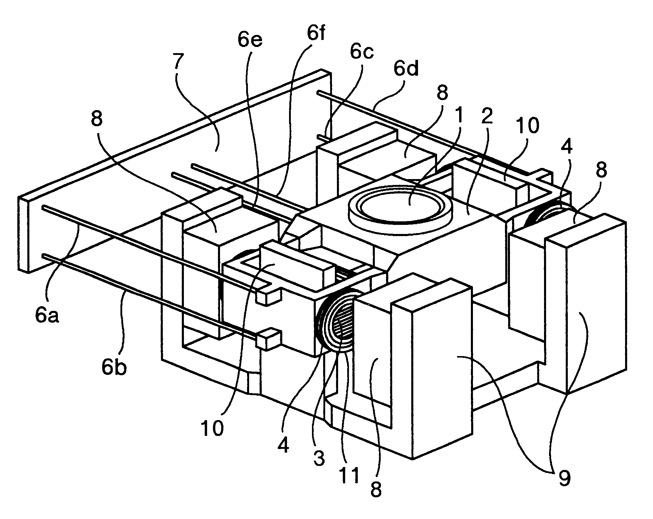
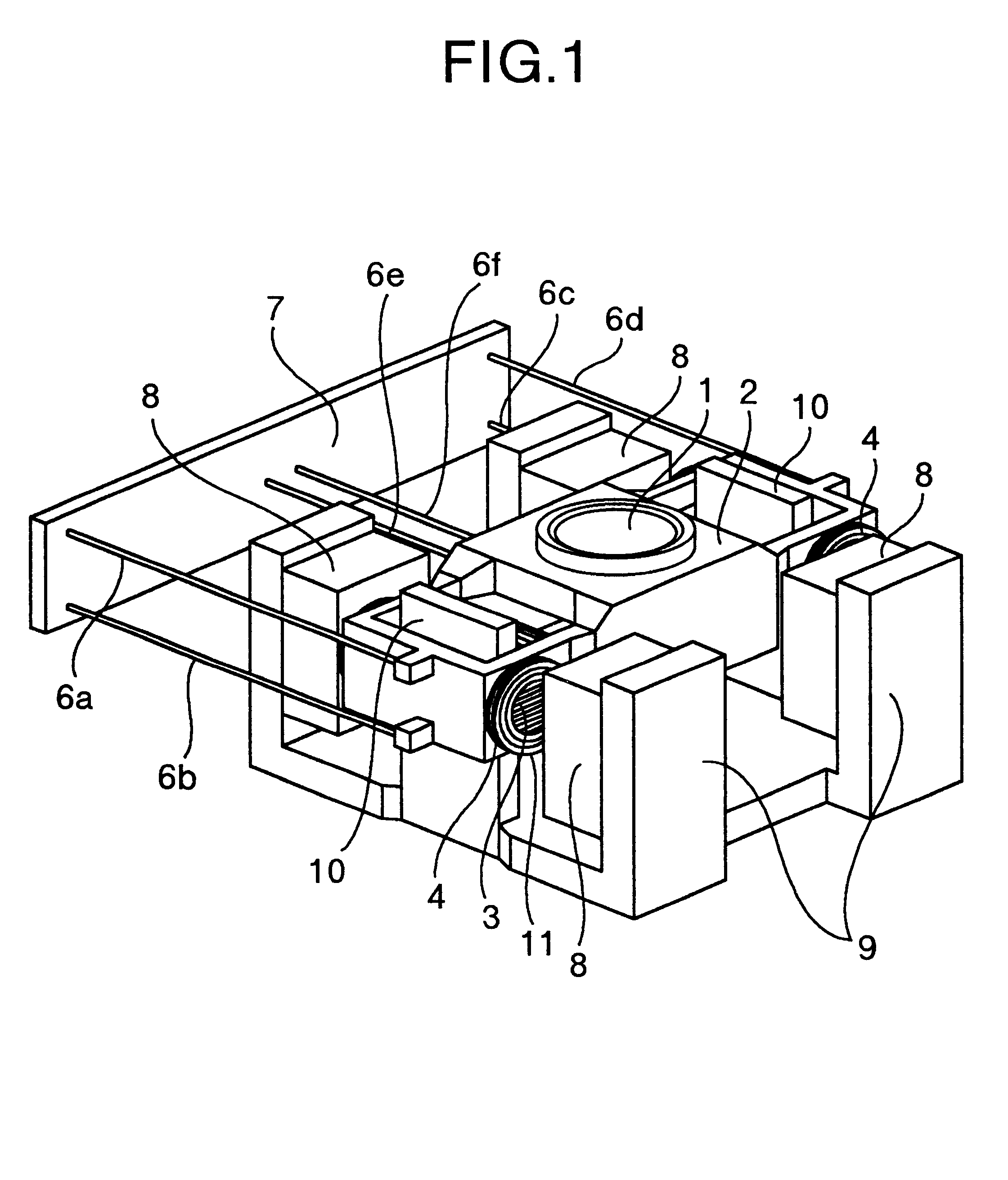
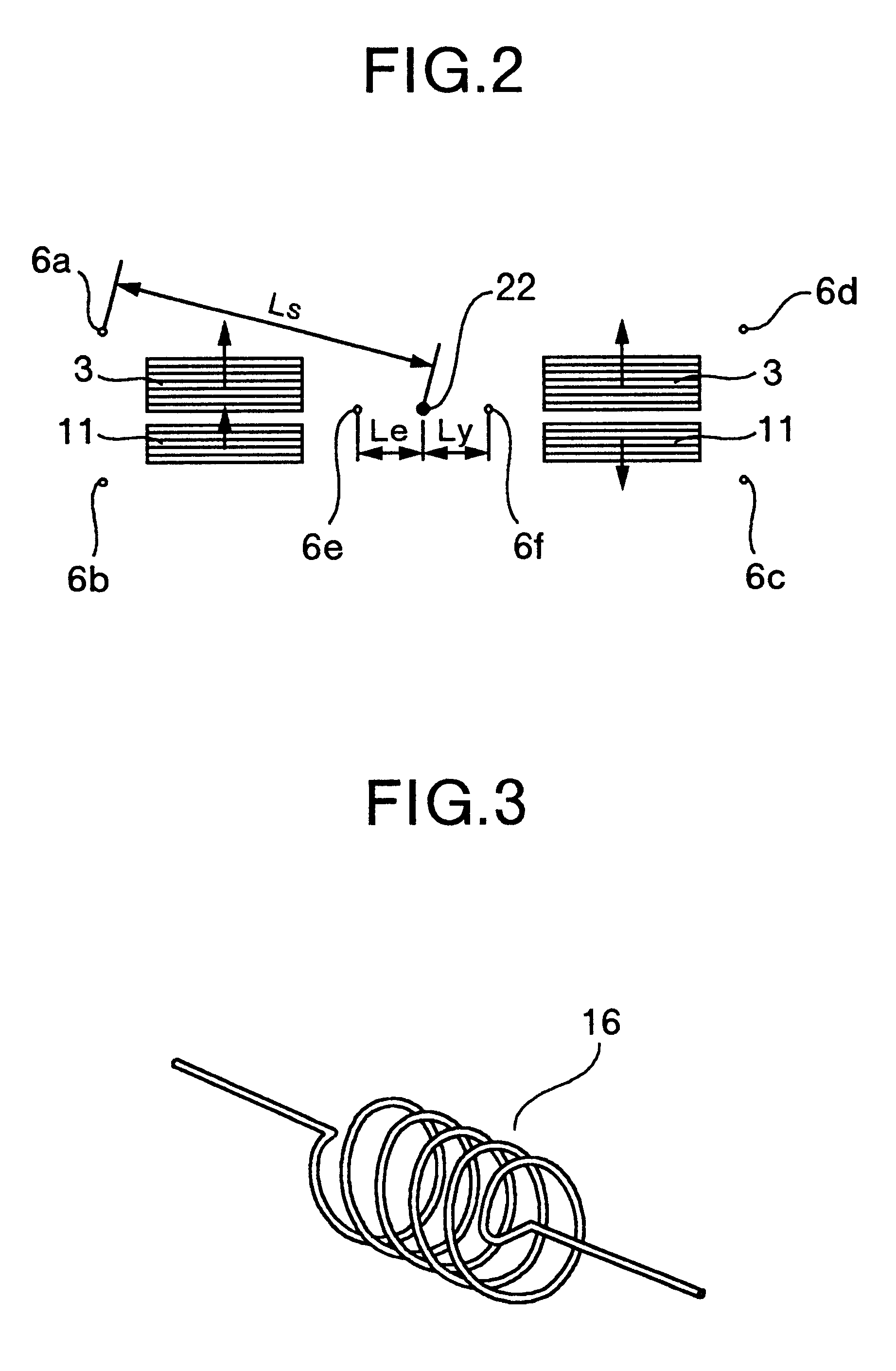
One embodiment of the present invention will be described below with reference to the drawings.

FIG. 7 is a perspective view showing an optical disk apparatus to which the present invention is applied.

A disk apparatus comprises a disk loading mechanism that conveys a disk 51 that is a disk-shaped information recording medium, into the device, subsequently mounts the disk 51 on a turntable provided around a rotating shaft of a spindle motor 52, and then fixes the disk 51. This disk loading mechanism comprises a disk tray 61, a loading motor which is not shown, a gear for transmitting a driving force of the motor, and a disk damper 53 for fixing the driving force transmitting member and the disk 51 to the turntable of the spindle motor 52.

A disk loading operation includes an operation of moving the disk tray 61, on which the disk 51 is placed during conveyance, into and out from a loading and unloading slit formed in a front panel 60 of the apparatus, in order to load or unload the dis...


PUM

PropertyMeasurementUnit
lengthaaaaaaaaaa
diameteraaaaaaaaaa
Poisson's ratioaaaaaaaaaa

Abstract

To provide an objective lens driving device that drives an objective lens for converging light on a recording surface of an optical disk, not only in a focusing and a tracking directions but also in an inclining direction of an optical axis of the objective lens, four support members are fixed to outer edge portions of a lens holder, and positions where the other support members are fixed to at least one of the lens holder and a fixing section are located inside the four support members fixed to the outer edge portions of the lens holder.

Description

The present invention relates to an optical disk apparatus, and in particular, to an optical disk apparatus comprising an objective lens driving device for driving an objective lens converging light on a recording surface, in a focusing direction, a tracking direction, and an inclining direction of an optical axis of the objective lens.To achieve appropriate recording and reproduction in optical disk apparatuses, in which the recording density is continuously improved, objective lens driving devices are required which drive an objective lens converging light on a recording surface of the optical disk apparatus, not only in a focusing and a tracking directions but also in an inclining direction of an optical axis of the objective lens, thereby correcting even the inclination of an optical disk. Such an objective lens driving device is disclosed in, for example, in JP-A-6-162540 specification or JP-A-10-275354 specification.In JP-A-6-162540 specification, a support member for supporti...

Claims


Application Information

Patent Timeline
Patent Type & Authority Patents(United States)
IPC IPC(8): G11B7/09G11B7/095
CPCG11B7/0932G11B7/0956
Inventor KIMURA, KATSUHIKOSATAKE, MITSUOWATANABE, MASAYOSHIITO, TETSUO
Owner HITACHI CONSUMER ELECTRONICS CORP
Why Eureka
Try Eureka