Device for immobilizing the ends shoe laces

a technology for shoe laces and ends, which is applied in the direction of shoe lace fastenings, eyelets, clothing, etc., can solve the problems of increasing production costs, known devices, and early wear of devices

Inactive Publication Date: 2003-01-07
DUBBERKE MARKUS
View PDF12 Cites 97 Cited by
  • Summary
  • Abstract
  • Description
  • Claims
  • Application Information

AI Technical Summary

Benefits of technology

The winding of the end potions of the ribbon makes it possible to provide a safe and uncomplicated securing of the end portions of the ribbons which are thus protected substantially against wear by bending, shearing, or tearing. The device according to the invention makes it possible to wind the end portions of the ribbon onto the hub element, for example, by a simple rotation of the cap element relative to the base element, so that further individual parts, especially spring means, can be dispensed with. This makes it possible to provide a simple and wear-protected manipulation at the device according to the invention.
It is especially preferred when the rim element is comprised of soft materials such as, for example, a soft plastic in order to achieve good gripping and handling of the device,

Problems solved by technology

The known devices, however, have a series of disadvantages.
Often, the known devices are comprised of relatively many individual parts, a fact which increases the production cost and may result in early wear of the devices.
In particular, some of the known devices have spring means for securing the shoe laces so that upon weakening of the spring properties of the spring means the devices become inoperable.
Furthermore, the known devices secure the shoe laces only in a relatively small area of the shoe laces with result that the fixation of the shoe laces is relatively weak and moreover, a large part of the shoe laces is accessible in an unprotected way.
This causes problems, in particular, for high top shoes with correspondingly long shoe laces.
The device described in EP 0693260 A2 has the disadvantage that the shoe laces due to the continuous circumference of the hub cannot be precisely received and guided into the circumferential groove.
A further disadvantage of the described device is the configuration of the hub which secured the shoe laces only unsatisfactorily, so that loosening of the shoe laces is possible.
Due to the axial-symmetrical shape and the continuous circumferences of the hub and the circumferential groove, as unsatisfactory clamping at the shoe laces results because only a radially acting tension force but not a tangentially acting tension force, resulting mainly from the turning action, clamps the shoe laces in the groove.
Further disadvantages of the prior art relates to unsatisfactory storage capacities of the known devices for the end portions of the ribbons and laces to be secured.
It is a disadvantage in this context that longer portions of, for example, shoe laces on high top shoes as well as clothing ribbons of jackets as well as their end portions, such as, for example, shoe lace tips, cannot be safely protected and stored in order to prevent soiling, wear, or the potential for an accident by getting caught or by tripping
Further disadvantages of the prior art are the unsatisfactory protection of the device with regard to functional disturbances by soiling, for example, in the "outdoor" field, and, furthermore, are to be seen in that a slipping of the devices relative to the shoe or the piece of clothing cannot be prevented so that in most cases both hands are required for operating the devices.
This is especially advantageous because the and portions or tips of the ribbon projected unprotectedly from the openings of the device and are thus exposed to dirt, wetness, and wear and presented an injury risk by tripping of getting caught.

Method used


Image

  • Device for immobilizing the ends shoe laces
  • Device for immobilizing the ends shoe laces
  • Device for immobilizing the ends shoe laces

Examples


first embodiment

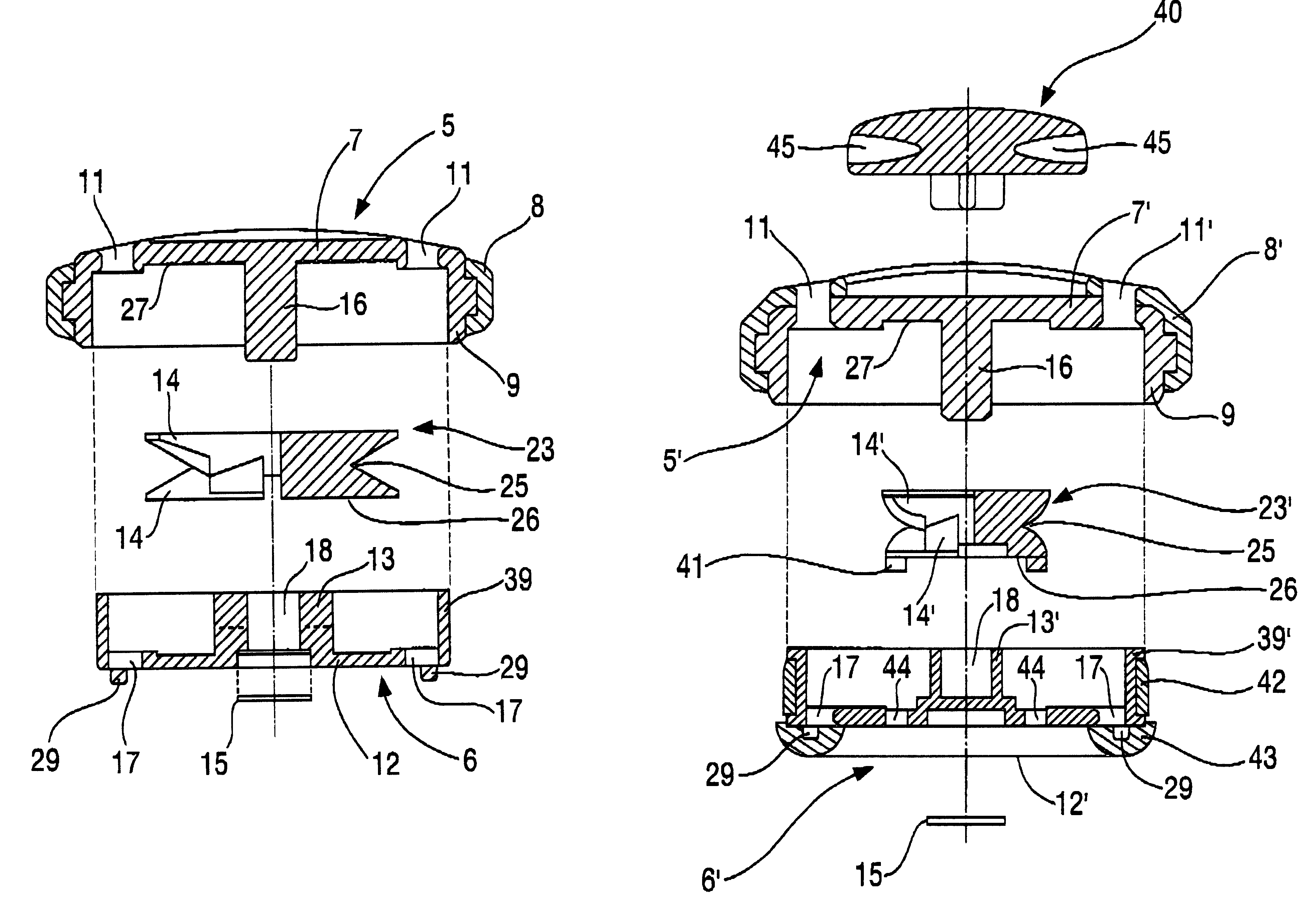
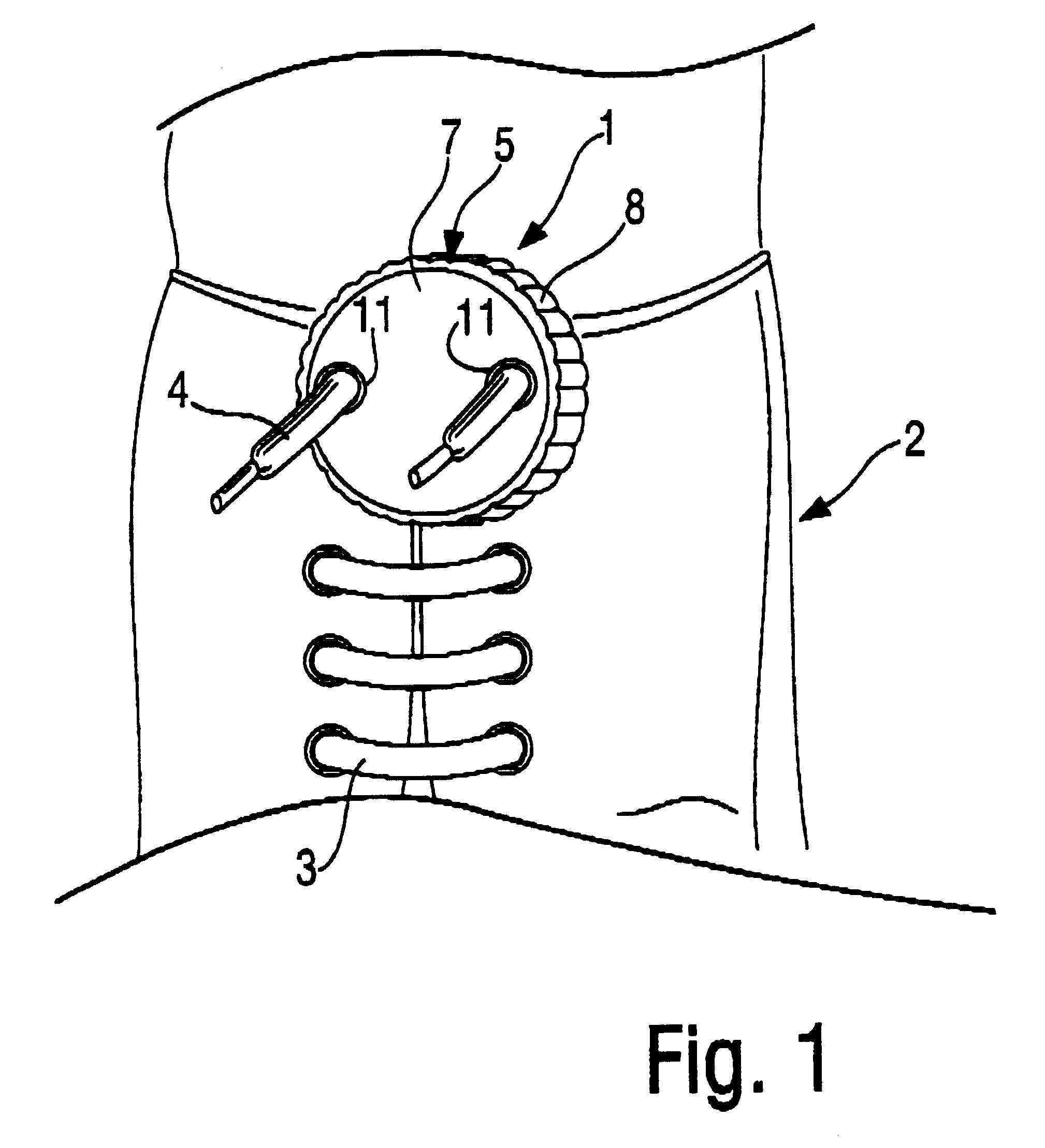
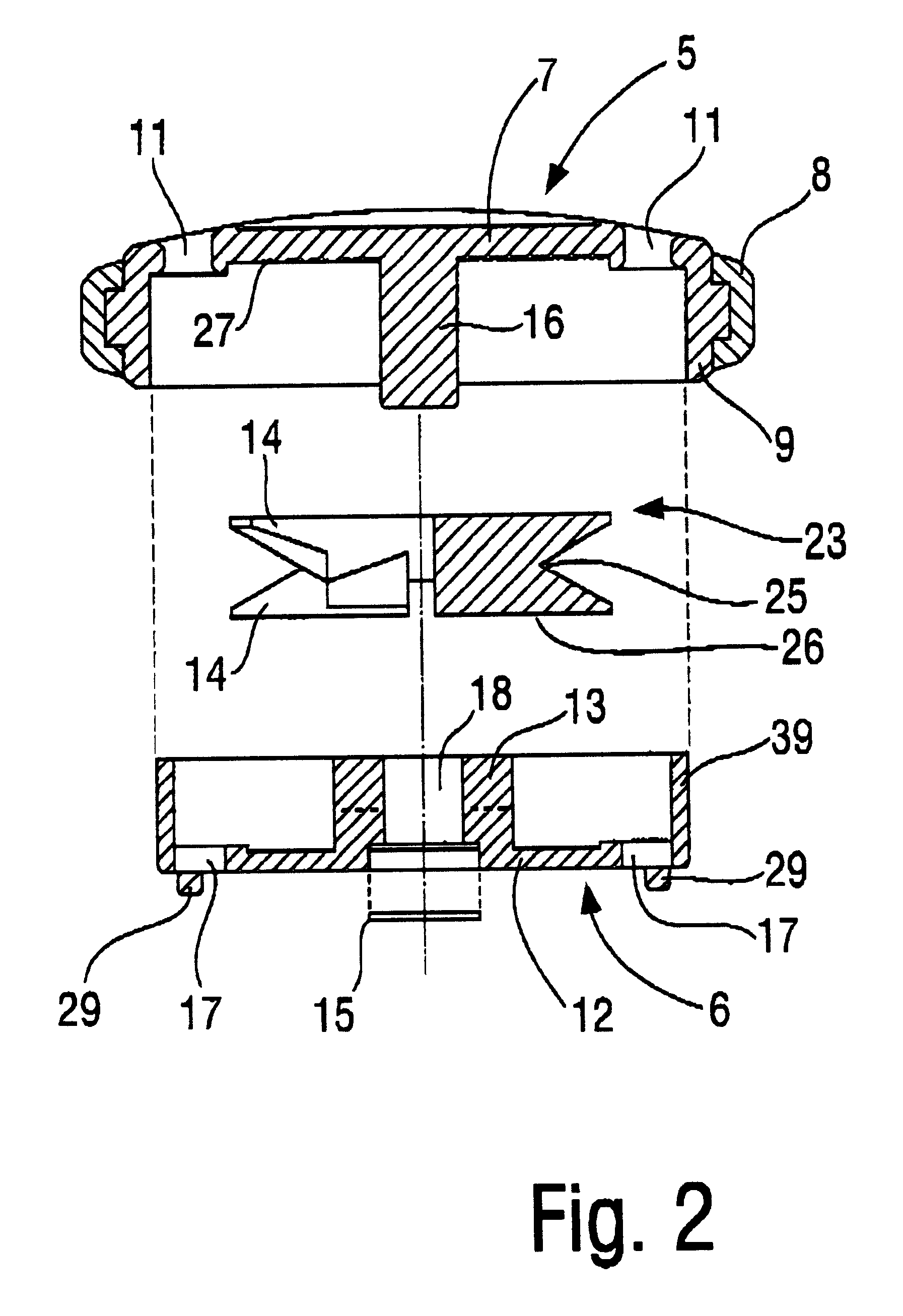
FIG. 2 shows a section of the device 1 according to the invention, comprising the cap element 5, the base element 6, and hub element 23. The base element 6 comprises a first flat structure 12 with a peg 13 projecting from the first flat structure and at least two openings 17 in the first flat structure spaced from the hub (FIGS. 2, 3a, and 3b). The cap element 5 comprises a second flat structure 7 and at least two spaced apart openings 11 (FIGS. 1, 2, 4a and 4b) which are arranged in the second flat structure 7 such that by at least one position of the cap element 5 relative to the base element 6 two openings in the first flat structure of the base element are aligned with two openings 11 in the second flat structure 7 of the cap element 6. The hub element 23 it axially symmetrical and non-rotatably connected to the peg 13 of the base element and the cap element is rotatable connected with base element 6 by means of the securing ring 15, wherein the second flat structure of the cap ...

second embodiment

FIG. 7 shows a section of the device 1 according to the invention, comprising the cap element 5', the base element 6' and the hub element 23'. The base element 6'comprises a first flat structure 12' with a peg 13' projecting from the first flat structure and, at least two openings 17 spaced from the hub in the first flat structure. The cap element 5' comprises a second flat structure 7' and two spaced apart openings 11 which are provided is the second flat structure 7 such that at least in one position of the cap element 5' relative to the base element 6' two openings in the first flat structure of the base element are aligned with two openings 11 in the second flat structure 7' of the cap element 6'. The hub element 23' in axially symmetrically placed onto the peg 13 of the base element and the cap element 5' is rotationally secured on the base element 6' by the securing ring 15, wherein the first flat structure 7' of the cap element 5' and the first flat structure 12' of the base ...


PUM


Abstract

A device (1) for securing end portions (4) of ribbon (3), including a base (6), having at least two openings (17), a cap (5), including at least two openings (11), wherein cap (5) and base (6) are rotatable relative to one another wherein openings (17) cooperate with two openings (11) such that opposite ends (4) of ribbon (3) are guided through respective pairs of cooperating openings (11, 17), and ends (4) can be wound up, characterized in that in the spacing between first flat structure (12) and second flat structure (7) a separate hub element (23) includes teeth (14) staggered to be positioned on the gaps relative to one another, wherein teeth (14) form a v-shaped groove (25), which is interrupted by alternatingly staggered gaps and tapers toward the interior of the hub element (23).

Description

The present application is a national stage filing under 35 U.S.C. .sctn. 371 of International Application PCT / EP99 / 02239 filed Apr. 1, 1999, which claims priority from German Patent Application 19814672.8, filed Apr. 1, 1998.The present invention relates to a device FOR securing ribbons or laces, especially for securing end portions of at least one shoe lace.PRIOR ARTProposals for such devices are described in EP 0314628 A2, EP 0693260 A2, FR 1518038, DE 4209425 C1, and U.S. Pat. No. 3,500,508, U.S. Pat. No. 3,345,707, U.S. Pat. No. 948,071. The devices described in the aforementioned documents are especially designed for children of kindergarten age who have not yet learned to tie a shoe laces themselves and are designed to facilitate or eliminate the tying of the shoes.For example, in DE4209425 C1 a press button for securing the shoe laces is described wherein a circular movement of an inwardly positioned ring effects that the shoe laces are clamped.In particular, in EP 0693260 A...

Claims


Application Information

Patent Timeline
Patent Type & Authority Patents(United States)
IPC IPC(8): A43C7/00
CPCA43C7/00Y10T24/3713Y10T24/3768Y10T24/3739Y10T24/3703Y10T24/3742
Inventor DUBBERKE, MARKUS
Owner DUBBERKE MARKUS
Why Eureka
Try Eureka