
Personnel guidance and location control system

a technology of location control and guidance, which is applied in the direction of traffic signals, instruments, roads, etc., can solve the problems of limiting the effectiveness of the system, incidents of theft and/or vandalism of either the pole or the cable, and the wear of the paint forming the line, and the need to re-paint the line again

Inactive Publication Date: 2002-04-25
PHARO DAN +1
View PDF0 Cites 17 Cited by
  • Summary
  • Abstract
  • Description
  • Claims
  • Application Information

AI Technical Summary

Benefits of technology

[0012] It is, therefore, one of the primary objects of the present invention to provide a personnel guidance and control system in which a ground covering substrate can be securely but nevertheless removably located on a ground surface and which has a guidance pathway formed thereon.
[0017] It is an additional object to the present invention to provide a personnel waiting guidance and control system of the type stated which is easily and readily installed and which is reusable and requires little or no maintenance to use.
[0019] It is also an object of the present invention to provide a system of protecting the heavily traveled portion of carpeting and like floor material from wear.
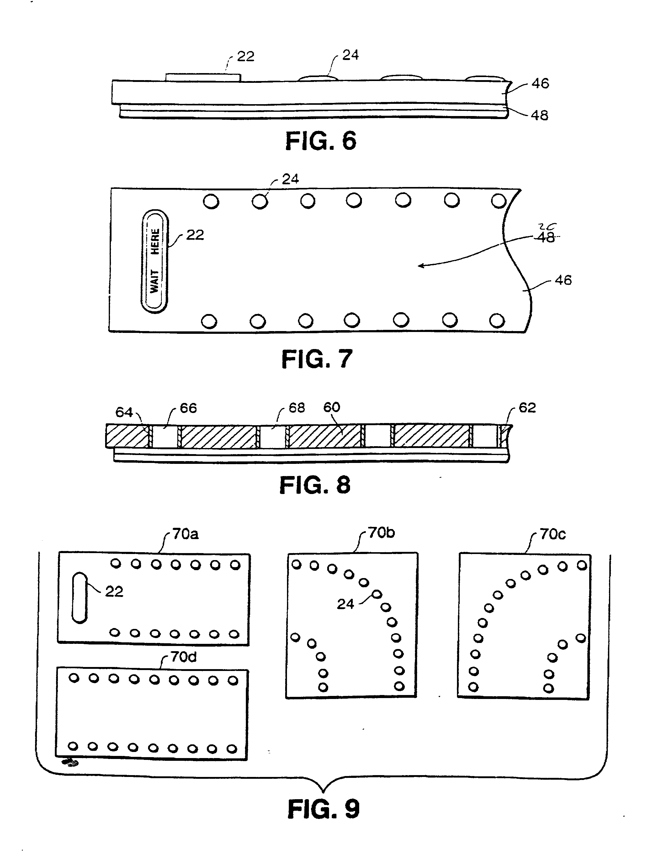
[0024] In a preferred embodiment of the invention, the individual discrete elements and the elongate element can all be formed, for example, in a piece of carpet material which is laid over a ground surface. This carpet material, in one embodiment, could have the discrete elements and the elongate element secured by means of fasteners on the underside of each of these elements. Nevertheless, when secured to the ground cover, such as the carpet in a desired location, installation is very quick and simple, in that the ground cover substrate is then secured to a ground surface.
[0036] In addition to the foregoing, both the elongate element and the discrete small members may have colored or reflective surfaces or sections thereof on their upper surface to further aid in guiding a path of movement of a group of individuals.

Problems solved by technology

Each of these commercially available guidance and control systems suffer from a number of drawbacks which somewhat limits their effectiveness.
First of all, where the movable poles are employed and hold a flexible cable, personnel waiting in the lines or others either intent on theft or vandalism can mischievously move the poles with the guidance cables extending therethrough to another location.
Secondly, when the poles and cables are located in an outside environment, they must be periodically removed and stored to prevent theft or vandalism, as for example, when the activity has closed.
Thirdly, even at a daytime or lighted period, there are also incidents of theft and / or vandalism to either the poles or cables or both.
Because of the heavy weighted body portions, the poles would spring back and strike the children attempting to push on same, thereby resulting in injury.
This again can result in the striking of an individual causing injury.
In the case of painted markers on the ground surface, such as a pair of spaced apart path defining lines, after a period of time, the paint forming these lines becomes worn and must again be repainted.
These activities are both time consuming and expensive and furthermore require periodic maintenance.
Another one of the problems with painted markers, such as painted lines, is the fact that it is virtually impossible to paint a straight line on certain ground surfaces, as for example, hand-laid tile surfaces.
Due to the unevenness of the tile, it is difficult to apply a straight line.
On dirt surfaces, movement of the dirt will cause disruption of the lines.
Again, tapes tend to rub off and after a short period of time become tattered, if not completely removed from the ground surface.
However, many facilities were not designed with extra space for such movement and, to accommodate disaled people, substantial space is rquired.

Method used


Image

  • Personnel guidance and location control system
  • Personnel guidance and location control system
  • Personnel guidance and location control system

Examples


Embodiment Construction

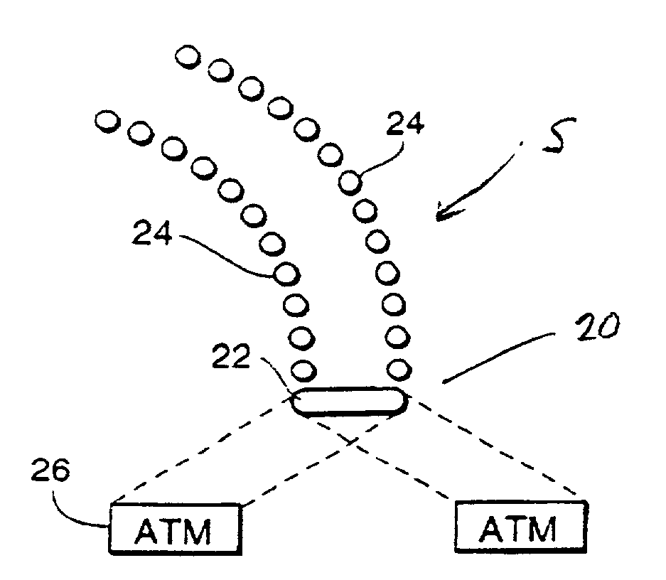
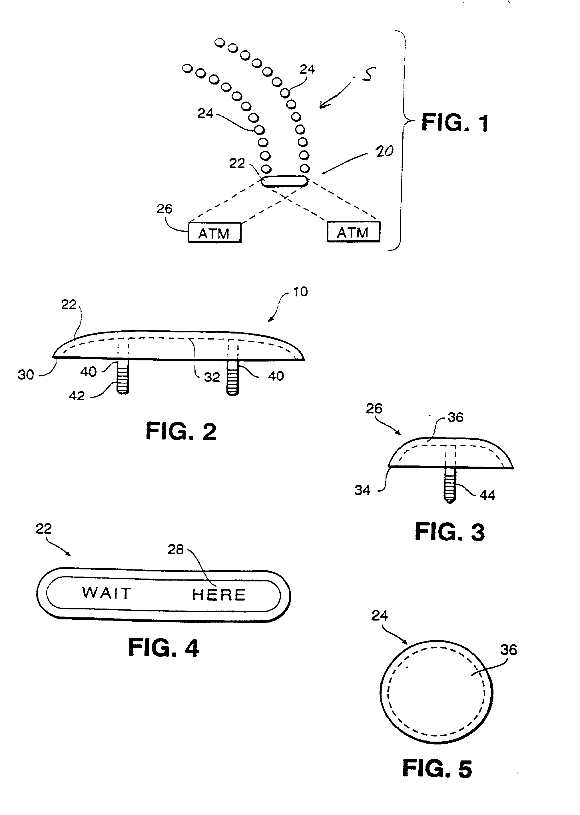
[0057] Referring now in more detail and by reference characters to the drawings which illustrate a preferred embodiment of the present invention, S designates a personnel guidance and location control system comprised primarily of a ground cover substrate 20, as hereinafter described in more detail. Mounted in the substrate 20 is an elongate element or member and referred to as a "head of the line" element 22 and a group of small discrete path defining elements 24.

[0058] The elongate element 22 and the path defining discrete elements 24 are preferably located on the ground cover substrate 20 in a particular arrangement to define a path of movement of a group of individuals in a waiting area so that each of the individuals may then advance to a selected activity or destination.

[0059] In accordance with the present invention, and merely for the purposes of illustrating the present invention, the personnel waiting guidance and control system shows the location of the entire substrate 2...


PUM


Abstract

A personnel location control system for controlling and guiding a group of individuals in a selected path to a waiting point and then to an activity in advance of that waiting point. The system in one embodiment relies upon a plurality of disks or like guide path-forming elements which define the edges of a desired guide path for a line of individuals waiting to reach the activity or destination. These elements may be physically mounted on a ground cover substrate where a single substrate or a plurality of similar substrates in combination, could form a desired guide path. Thus, some of the ground substrates may define arcuate guide path sections and others may define straight guide path sections, etc., but which when combined will form a total guide path. Thus, modular carpet substrates or sections could be provided and each of these carpet sections would be capable of being secured to a ground or floor surface. In another embodiment, the guide forming elements may be integrally formed in the carpet substrates. Further, the guide forming elements may be individual carpet pieces which are located in holes formed in the carpet substrates. Thus, the various carpet substrates could all be pre-formed and merely secured to a floor at a desired location.

Description

[0001] 1. Field of the Invention[0002] This invention relates in general to certain new and useful improvements in a personnel waiting guidance and control system for guiding a group of individuals in a controlled manner and through a selected path to a particular activity.[0003] 2. Brief Description of Related Art[0004] Personnel guidance and control systems have long been used in a variety of activities for controlling the path of movement of a group of individuals to an activity. As a few simple examples, these guidance and control systems have been used for controlling a group of people waiting for one or more tellers in a banking institution or otherwise a group of people waiting to use a series of one or more automated teller machines. In like manner, these guidance and control systems are frequently used for various entertainment and amusement activities to control a group of people who are desirous of entering the activity. These systems form a selected path for entry in a c...

Claims


Application Information

Patent Timeline
Patent Type & Authority Applications(United States)
IPC IPC(8): E01F9/06G07C11/00G09F19/22
CPCE01F9/065G09F19/22G07C2011/04G07C11/00E01F9/559
Inventor PHARO, DANHEMBREE, ALEX J.
Owner PHARO DAN
Learn More