High pressure discharge lamp driving apparatus, luminaire and high pressure discharge lamp driving method

a technology of high pressure discharge and driving apparatus, which is applied in the direction of electric variable regulation, process and machine control, instruments, etc., can solve the problems of electrode substance being exhausted by sputtering, flickering of color or brightness on a picture, and prior art cannot achieve the operation or effect of reducing so as to reduce the fluctuation of emitted light and control the flickering of the output amount of ligh

Inactive Publication Date: 2003-01-07
HARISON TOSHIBA LIGHTING CORP
View PDF5 Cites 37 Cited by
  • Summary
  • Abstract
  • Description
  • Claims
  • Application Information

AI Technical Summary

Benefits of technology

An object of the present invention is to provide a high pressure discharge lamp driving method, a high pressure discharge lamp driving apparatus, and a luminaire utilizing the high pressure discharge lamp driving apparatus, which decrease the a fluctuation of emitted light in half-cycle period of the lamp current, so as to control flickering of the output amounts of light.
In the first aspect of the invention, it is possible to heat the electrode fully to the very end part of the second half of the half-cycle period. As a result, it is possible to keep the electrode temperature high to a required level in the next half-cycle period after the polarity fluctuation of the lamp current. Accordingly, when an action of electrode has switched from an anodic phase to a cathodic phase, it is controlled that a cathode spot moves over the electrode surface, thus the stability of the discharge is enhanced.
Furthermore, it is hard to produce a sputtering of the electrode substance caused by the electrode pulse at about the end of half-cycle period, so that the life of the high pressure discharge lamp is improved.

Problems solved by technology

Accordingly, the prior art has a drawback that a rapid change of the output amounts of light by superposing the pulse current on the lamp current causes flickering of color or brightness on a picture even if for a short time, in case of using a light emitted for extremely short time such as the digital light processing (trade name; "DLP") system which obtains a color picture by superposing the RGB three-primary-color picture by timesharing and then projecting the picture by utilizing a revolving RGB color filter and a digital micro-mirror device (trade name; "DMD").
Therefore, the prior art could not achieve an operation or effect of reducing the flickering of the output amounts of light in regard to a usage pattern of the output amounts of light.
Also, in the prior art, an electrode substance tends to be exhausted by sputtering when the electrode is heated by superposed on the pulse current.
Therefore, the prior art has another drawback that since the inner surface of a translucent discharge bulb is blackened to decrease the transparency of the bulb, the life of the high pressure discharge lamp is shortened as the output amounts of light decreases.

Method used


Image

  • High pressure discharge lamp driving apparatus, luminaire and high pressure discharge lamp driving method
  • High pressure discharge lamp driving apparatus, luminaire and high pressure discharge lamp driving method
  • High pressure discharge lamp driving apparatus, luminaire and high pressure discharge lamp driving method

Examples


first embodiment

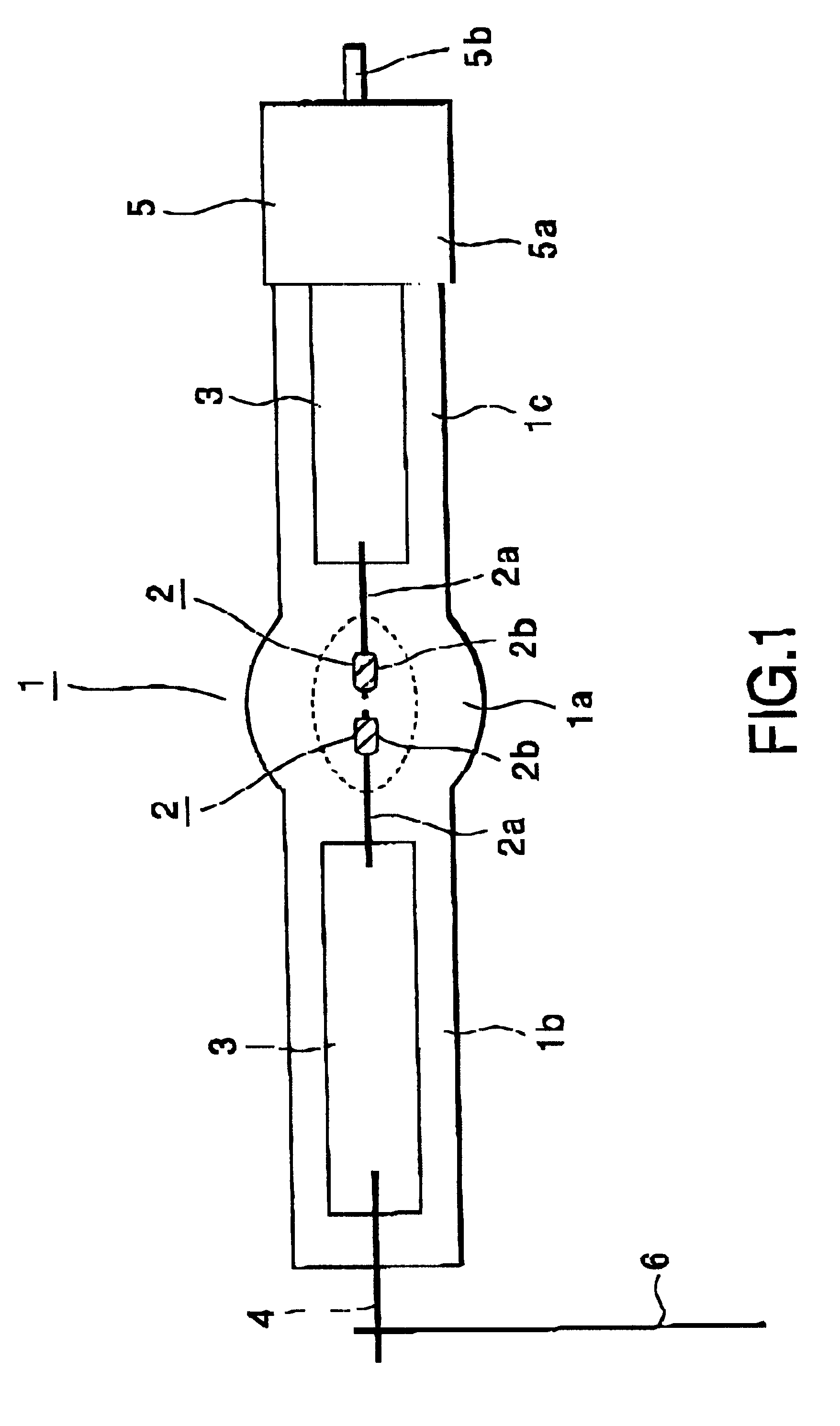
FIG. 1 is showing a front section of the high pressure discharge lamp in the high pressure discharge lamp driving method according to the present invention.

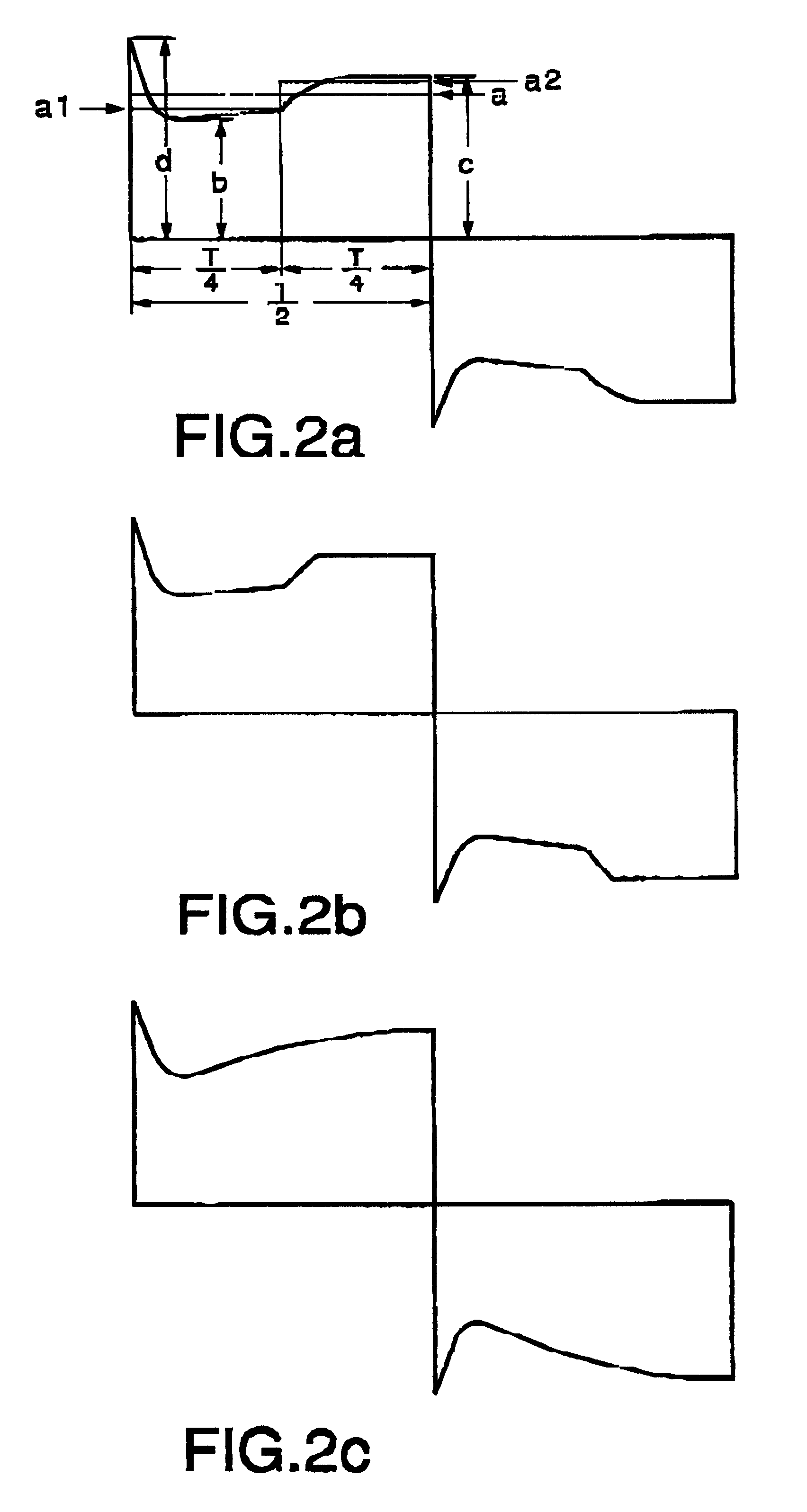
FIGS. 2a to 2e are waveform diagrams showing acceptable aspects of the AC lamp current in the high pressure discharge lamp driving method.

FIG. 3 is waveform diagrams showing other acceptable aspects of the AC lamp current in the high pressure discharge lamp driving method.

First, the high pressure discharge lamp will be explained.

In FIG. 1, 1 denotes a translucent discharge bulb, 2 denotes a pair of electrodes, 3 denotes a sealed end metal foil, 4 denotes a lead-conductor, 5 denotes a bulb-base, and 6 denotes a connecting-conductor.

The translucent discharge bulb 1, which is made of a silica glass, is comprised of an envelope 1a at the center and a first and a second reduced pressure portions to be sealed 1b, 1c on both edges of the envelope 1a. The first and the second portions to be sealed 1b, 1c are integrally fabricated on both...

second embodiment

The second embodiment differs from the first embodiment in that the high pressure discharge lamp is driven by the AC lamp current which does not have the maximum value immediately after polarity change. That is, FIG. 4a is showing a waveform where the instantaneous value rises linearly of the first half of each half-cycle period and becomes a rectangle-shape in the second half.

FIG. 4b is showing a waveform where the instantaneous value rises linearly throughout the half-cycle period.

FIG. 4c is showing a waveform where the instantaneous value rises gradually of the first half of each half-cycle period and becomes a rectangular shape in the second half.

FIG. 4d is showing a waveform where the instantaneous value falls in part in a middle part of the first half of half-cycle period, while it rises gradually before and after the middle part, and it becomes a rectangle-shape in the second half.

Here, the AC lamp current which does not have a maximum value immediately after polarity change ...

third embodiment

Next, in relation to the high pressure discharge lamp according to the present invention, a result of testing for checking existence of the movement of luminescent spot and the blackening of discharge bulb in the case that the high pressure discharge lamp is operated at different ratios a / b. c / d and d / a by controlling the AC lamp current waveform will be explained referring to Tables 1 through 3. The contents of evaluation of the evaluation signs about the movement of luminescent spot and the blackening in a table will be shown hereinafter.

The movement of luminescent spot. .largecircle.: there is not the movement of luminescent spot .DELTA.: there is a little movement of luminescent spot X : there is remarkable movement of luminescent spot.

Blackening of Translucent Discharge Bulb. .circleincircle.: Blackening had not occurred until 5000 hours of lighting. .largecircle.: Blackening had not occurred until 2000 hours of lighting. .DELTA.: Blackening had not occurred until 1000 hours of...


PUM


Abstract

Disclosed a high pressure discharge lamp driving apparatus for driving a high pressure discharge lamp during a stable operation thereof with an AC lamp current alternating for opposite half-cycle periods, the apparatus comprising an AC lamp current supply for supplying the AC lamp current to the high pressure discharge lamp, a detector for detecting the output AC lamp current to the high pressure discharge lamp, a controller responsive to the detector for controlling the AC supply to output the AC lamp current with a waveform which is characterized by that (i) a mean value in the second half of each half-cycle period is larger than the means value of the first half of each half-cycle period, (ii) no pulse current is contained in the second half of each half-cycle period, (iii) the AC lamp current has a maximum value immediately after polarity change between the positive and negative half-cycle periods, and (iv) the AC lamp current has also a waveform defined by that the ratio (d / a) of the maximum value (d) of the AC lamp current and a mean value (a) of the AC lamp current in its each half-cycle period satisfies a following equation.

Description

FIELD OF THE INVENTIONThe present invention relates to a high pressure discharge lamp driving apparatus, a luminaire and high pressure discharge lamp driving method.BACKGROUND OF THE INVENTIONPCT application Japanese laid-open patent Toku-Hyo-Hei 10-501919 (PCT / ID95 / 00392) discloses an apparatus and method for driving a high pressure discharge lamp with an AC lamp current, wherein a pulse current is generated in a predetermined fraction of a half-cycle period of lamp current, and the polarity of the pulse current is made the same as the lamp current, then the pulse current is superposed on the lamp current in the second half of each half-cycle period where it is generated.It is also described that good results may be achieved when the ratio between the mean amplitudes of the pulse current and the lamp current is in the range of 0.6 to 2, and the ratio between the duration of the pulse current and the half-cycle period of the lamp current is in the range of 0.05 to 0.15.In the prior ...

Claims


Application Information

Patent Timeline
Patent Type & Authority Patents(United States)
IPC IPC(8): H05B41/28H05B41/292H05B41/24H05B41/282
CPCH05B41/2887H05B41/2928Y02B20/208Y02B20/202Y02B20/00
Inventor YUDA, TOKUJIKATOH, JUNICHI
Owner HARISON TOSHIBA LIGHTING CORP
Why Eureka
Try Eureka