Remote sensing by high-order filtering

a filtering and high-order technology, applied in the direction of electric variable regulation, process and machine control, instruments, etc., can solve the problems of not allowing for a wide bandwidth closed-loop system, not improving the closed-loop stability of the system, and creating distortion

Inactive Publication Date: 2003-01-07
HARMAN INT IND INC
View PDF5 Cites 12 Cited by
  • Summary
  • Abstract
  • Description
  • Claims
  • Application Information

AI Technical Summary

Problems solved by technology

In practice, this does not allow for a wide bandwidth closed-loop system, as the impedances between the source and the load form a low-pass filter which adds phase lag to the feedback and thus does not improve the closed-loop stability of the system.
If all voltage feedback is taken at the input to the filter, on the other hand, the feedback signal will include large amounts of pulse width modulation (PWM) ripple which will create distortion if introduced into the control loop.
Similar issues are associated with current feedback signals.
The performance of this system can be jeopardized when the series impedance between the actual signal source and the load acts as a high-Q inductance and the load contains a high-Q shunt capacitance.
Instability may result when the gain margin of the feedback loop is overwhelmed by the gain peak of this resonance.
In both cases, the Q of the inductances must be high or conduction losses will be severe.

Method used


Image

  • Remote sensing by high-order filtering
  • Remote sensing by high-order filtering
  • Remote sensing by high-order filtering

Examples


Embodiment Construction

The embodiments disclosed below are not intended to be exhaustive or limit the invention to the precise forms disclosed in the following detailed description. Rather, the embodiments are chosen and described so that others skilled in the art may utilize their teachings.

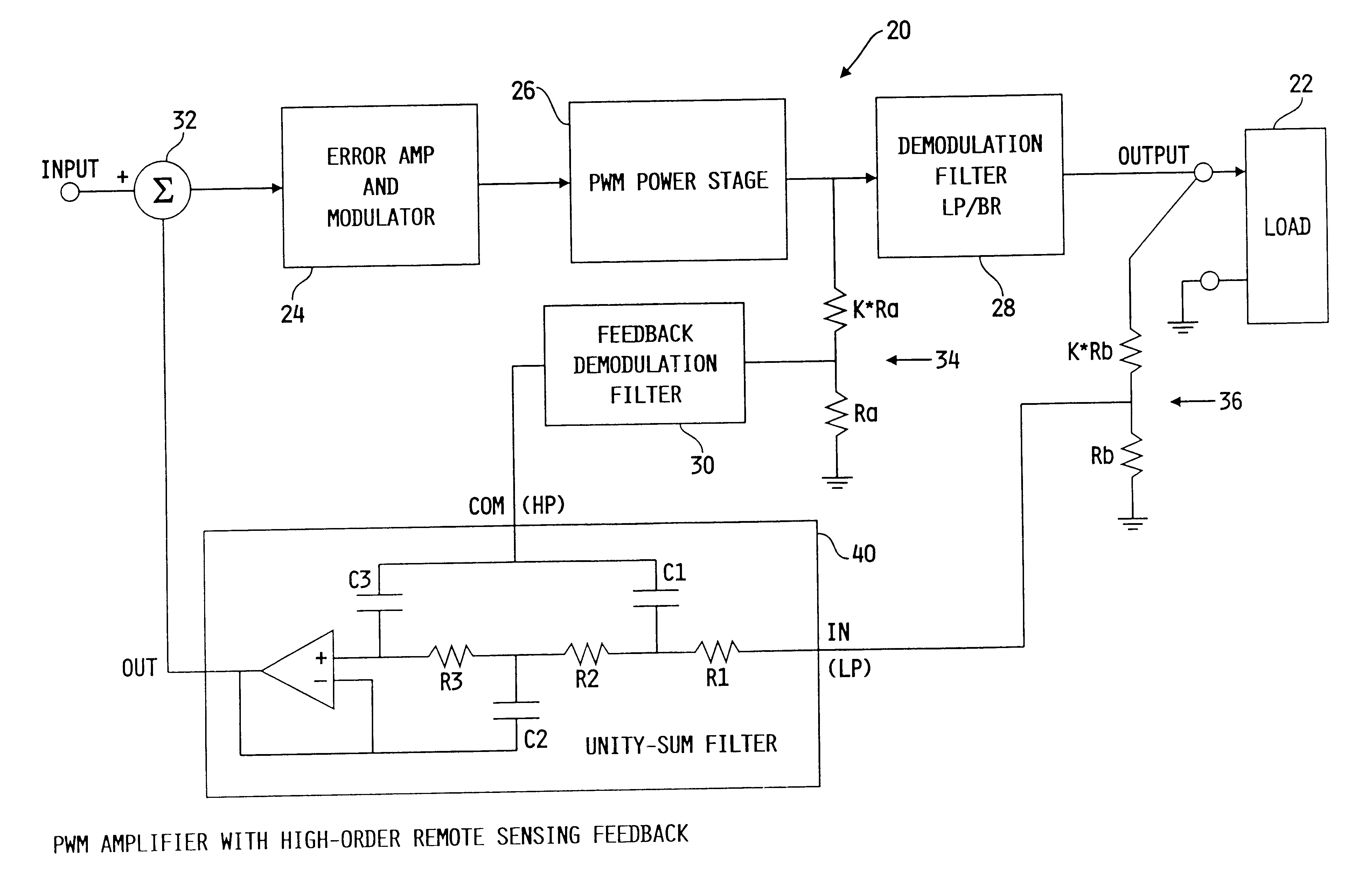
Referring now to FIG. 3, an amplifier in accordance with the present invention and generally referenced as 20, is shown connected to a load 22. Amplifier 20 includes an error amplifier and modulator 24, a pulse width modulation (PWM) power stage 26, a demodulation filter 28, a feedback demodulation filter 30, and voltage dividers 34, 36.

Amplifier 20 is an opposed current amplifier with a low-pass feedback signal and a high-pass feedback signal combined at high-order filter 40 as further described below. Amplifier 20 actively filters the low-pass feedback signal with demodulation filter 28 and the high-pass feedback signal with demodulation feedback filter 30.

Demodulation filter 28, which is a low-pass filter combined ...


PUM


Abstract

A power converter having a remote sensing system. The power converter includes a high-pass feedback signal, a remote sensing low-pass signal, a constant-sum filter combining the high-pass feedback signal and the remote sensing low-pass signal. The constant-sum filter is at least a second order filter and generates an error signal. The constant-sum filter is a three terminal low-pass filter and an input terminal, an output terminal, and a common terminal. The input terminal receives the remote sensing low-pass signal. The common terminal receives the high-pass feedback signal. The output terminal transmits the feedback control signal.

Description

1. Field of the InventionThe present invention generally relates to the regulation of power converters and more particularly to the regulation of amplifiers using remote sensing to control the signal at the amplifier load.2. Description of the Related ArtIt is often desired to improve the regulation of a voltage source at its load by sensing and controlling the actual voltage produced at the load. Such remote sensing, as it is called, overcomes limitations of finite source impedance which derives from the impedance of connecting cables, connectors, filters, etc., that lie between a signal source and a load. In the simplest of situations, one would derive all controlling feedback from the voltage induced across the load.In practice, this does not allow for a wide bandwidth closed-loop system, as the impedances between the source and the load form a low-pass filter which adds phase lag to the feedback and thus does not improve the closed-loop stability of the system.This filter / stabil...

Claims


Application Information

Patent Timeline
Patent Type & Authority Patents(United States)
IPC IPC(8): H03F3/217H03F3/20H02M3/156H02M3/335
CPCH02M3/156H03F3/217H02M3/33507
Inventor STANLEY, GERALD R.
Owner HARMAN INT IND INC
Why Eureka
Try Eureka