Parallel arranged linear amplifier and dc-dc converter

a technology of linear amplifier and parallel arrangement, which is applied in the direction of amplifiers, amplifiers with semiconductor devices/discharge tubes, instruments, etc., can solve the problems of high frequency of dc-dc converter supplies, relative slow dc-dc converter supplies, etc., and achieve the effect of not jeopardizing the stability of the control loop

Inactive Publication Date: 2010-02-25
NXP BV
View PDF10 Cites 91 Cited by
  • Summary
  • Abstract
  • Description
  • Claims
  • Application Information

AI Technical Summary

Benefits of technology

[0018]The DC current through the resistor in parallel with the extra inductor is relatively small because the resistance of the resistor is relatively large with respect to the resistance of the inductor with which the series arrangement is arranged in parallel. This parallel arrangement can be obtained by two equivalent circuits. In the first circuit, the inductor is arranged in series with the damping resistor, and the series arrangement is arranged in parallel with the second inductor which is arranged in the main current path between the first inductor and the load. In a second circuit, the inductor is arranged in parallel with the damping resistor, and the parallel arrangement is arranged in series with the second inductor. A same reasoning holds for low frequency currents. On the other hand the HF suppression of the filter is optimal because it is not degraded to a first order filter.
[0019]In an embodiment as claimed in claim 2, the second current provides the DC and low frequency portion of the load current, and the first current provides the high frequency portion of the load current. A crossover frequency is defined as the frequency at which the magnitude of the high frequency contribution is equal to the magnitude of the DC and low frequency contribution. The bandwidth of the low-pass filter is selected above the crossover frequency such that its current transfer magnitude is sufficiently large at the crossover frequency and the filter does not jeopardize the control loop stability.

Problems solved by technology

The relatively slow DC-DC converter supplies the DC and low frequent currents to the load at relatively high power efficiency, and the relatively power inefficient linear amplifier supplies the high frequent currents to the load only.

Method used


Image

  • Parallel arranged linear amplifier and dc-dc converter
  • Parallel arranged linear amplifier and dc-dc converter
  • Parallel arranged linear amplifier and dc-dc converter

Examples


Embodiment Construction

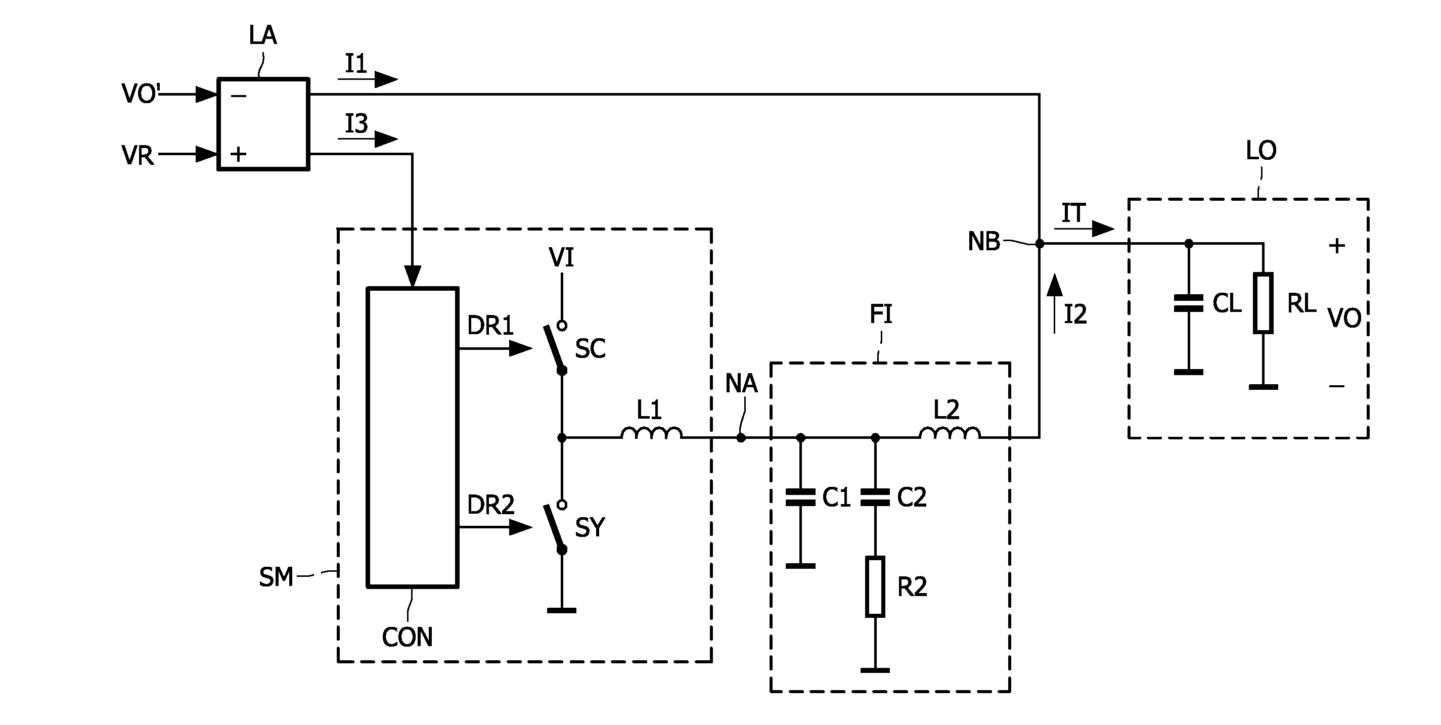
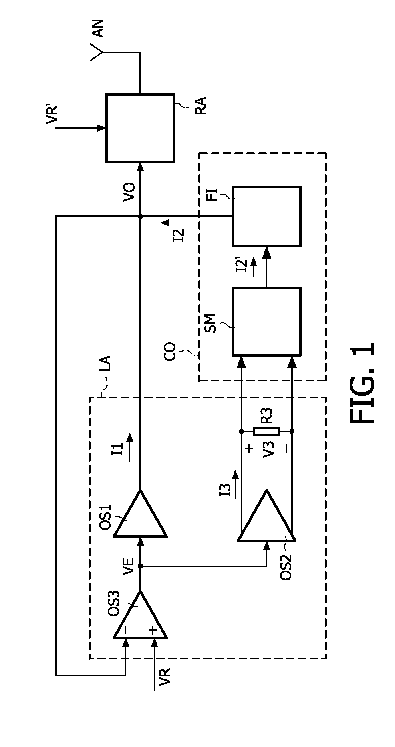
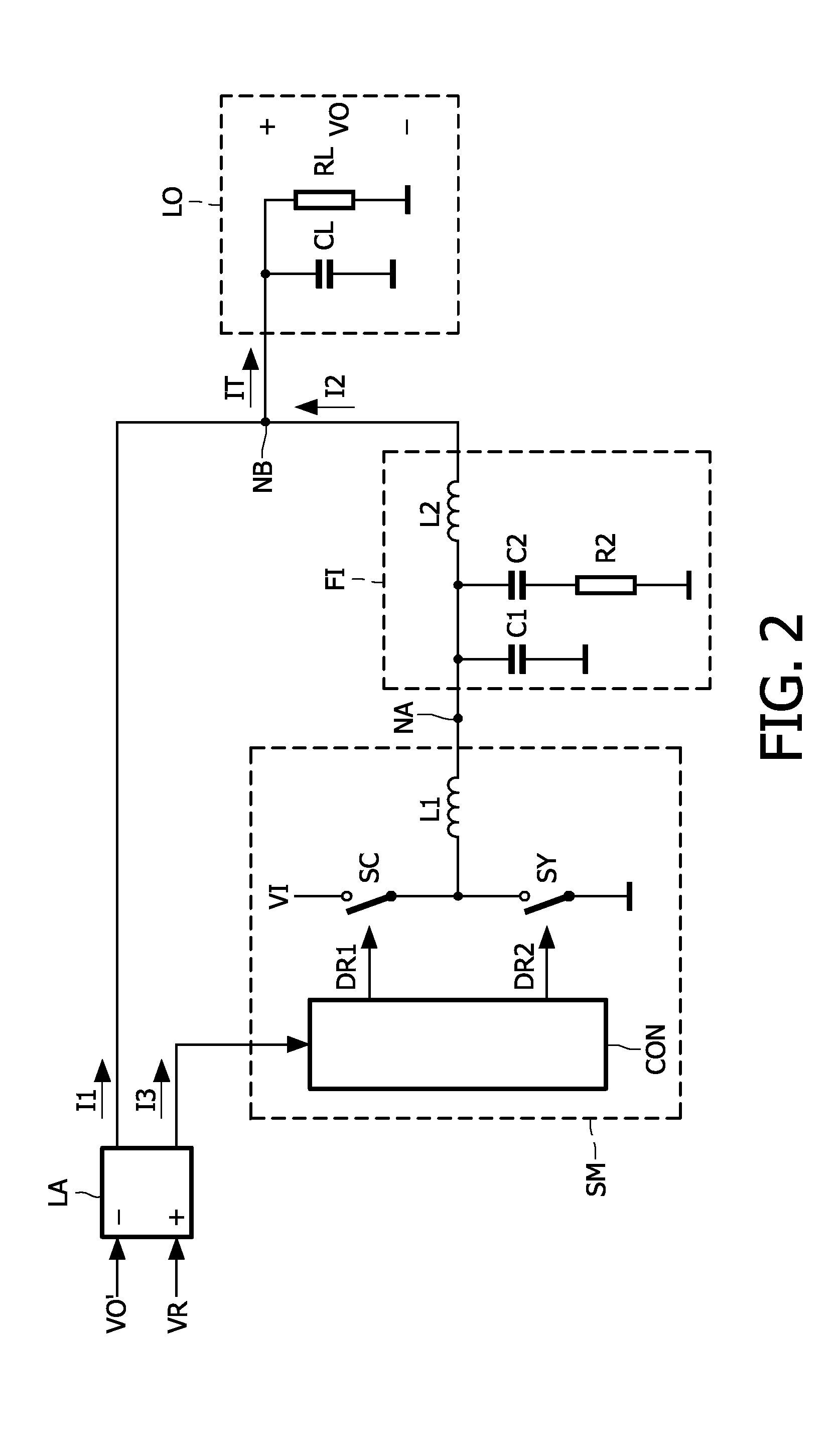
[0035]FIG. 1 shows a block diagram of an apparatus which comprises the power supply system in accordance with the invention. By way of example only, the apparatus shown is a telecom system. The power supply system is advantageous in any other apparatus which requires an efficient and fast power supply which is able to change the output voltage at a fast speed, or which is able to respond quickly to a change in the load of a circuit of the apparatus.

[0036]A power efficient RF (high frequency) power amplifier RA for use in, for example, 2.5G, 3G, or 4G telecom systems requires a fast and power efficient supply modulator. This supply modulator or power supply system supplies a rapidly varying supply voltage VO to the RF power amplifier RA. The supply voltage VO fits the output power to be supplied by the RF power amplifier RA. A fast and accurate control of the supply voltage VO, and thus of the current supplied by the power supply system, is especially important in handheld battery op...


PUM


Abstract

A power supply system comprises a parallel arrangement of a linear amplifier (LA) and a DC-DC converter (CO). The linear amplifier (LA) has an amplifier output to supply a first current (II) to the load (LO). The DC-DC converter (CO) comprises: a converter output for supplying a second current (12) to the load (LO), a first inductor (L1), and a switch (SC) coupled to the first inductor (L1) for generating a current in the first inductor (L1), and a low-pass filter (FI) arranged between the first inductor (L1) and the load (LO). The low pass filter (FI) comprises a first capacitor (C1; CA) which has a first terminal coupled to the switch (SC) an a second terminal coupled to a reference voltage level (GND), and a second inductor (L2; LC) which has a first terminal coupled to the first inductor (L1) and a second terminal coupled to the load (LO). The low-pass filter further comprises, either: (i) a series arrangement of a second capacitor (C2) and a damping resistor (R2), which series arrangement is arranged in parallel with the first capacitor (C1), or (ii) a parallel arrangement of a third capacitor (CB) and a damping resistor (RB) arranged in series with the first capacitor (CA), or (iii) a series arrangement of a third inductor (L3) and a damping resistor (R3), which series arrangement is arranged in parallel with the second inductor (L2), or (iv) a parallel arrangement of a fourth inductor (LD) and a damping resistor (RD), which parallel arrangement is arranged in series with the second inductor (LC).

Description

FIELD OF THE INVENTION[0001]The invention relates to a power supply system with a parallel arrangement of a linear amplifier and a DC-DC converter, and an apparatus comprising such a power supply system.BACKGROUND OF THE INVENTION[0002]U.S. Pat. No. 5,905,407 discloses a high efficiency power amplifier using combined linear and switching techniques with a feedback system. A linear amplifier supplies an output current to a load via a sense resistor. A switching amplifier which comprises a controllable switch and two series arranged LC-sections is used as a DC-DC converter and supplies a further output current to the load. The resistor is arranged between the output of the linear amplifier and the output node of the power supply system at which the output voltage is present across the load. The output current of the linear amplifier flows through this resistor. The voltage across the resistor is used to control the DC-DC converter to obtain a minimal DC-component of the output current...

Claims


Application Information

Patent Timeline
Patent Type & Authority Applications(United States)
IPC IPC(8): G05F1/10
CPCH03F3/211H03F2200/432H03F3/217
Inventor BLANKEN, PIETER G.MOORE, PAUL ANTHONYREEFMAN, DERKMINNIS, BRIAN
Owner NXP BV
Why Eureka
Try Eureka