
Torque and power control in a powertrain

a powertrain and torque technology, applied in the direction of electric control, gearing control, gearing elements, etc., can solve the problems of detriment to the operation of the powertrain, and achieve the effect of improving torque and power control of the powertrain

Inactive Publication Date: 2003-01-28
GM GLOBAL TECH OPERATIONS LLC
View PDF17 Cites 50 Cited by
  • Summary
  • Abstract
  • Description
  • Claims
  • Application Information

AI Technical Summary

Benefits of technology

It is an object of the present invention to provide a

Problems solved by technology

Each of these elements as well as the shafts in the transmission have a maximum torque capacity which, if exceeded, may be detrimental to the operation of the powertrain.

Method used


Image

  • Torque and power control in a powertrain
  • Torque and power control in a powertrain
  • Torque and power control in a powertrain

Examples


Embodiment Construction

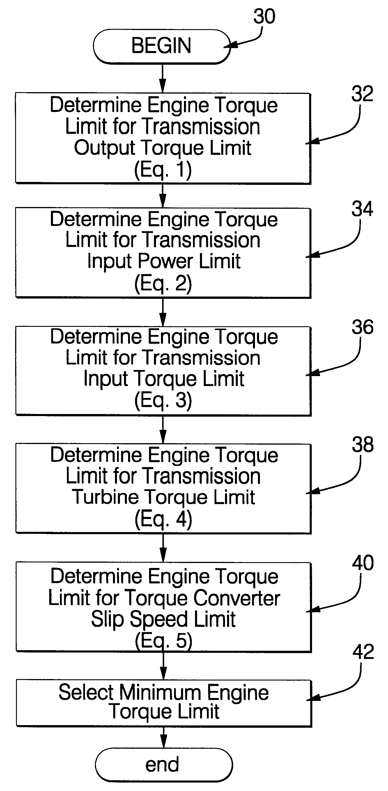
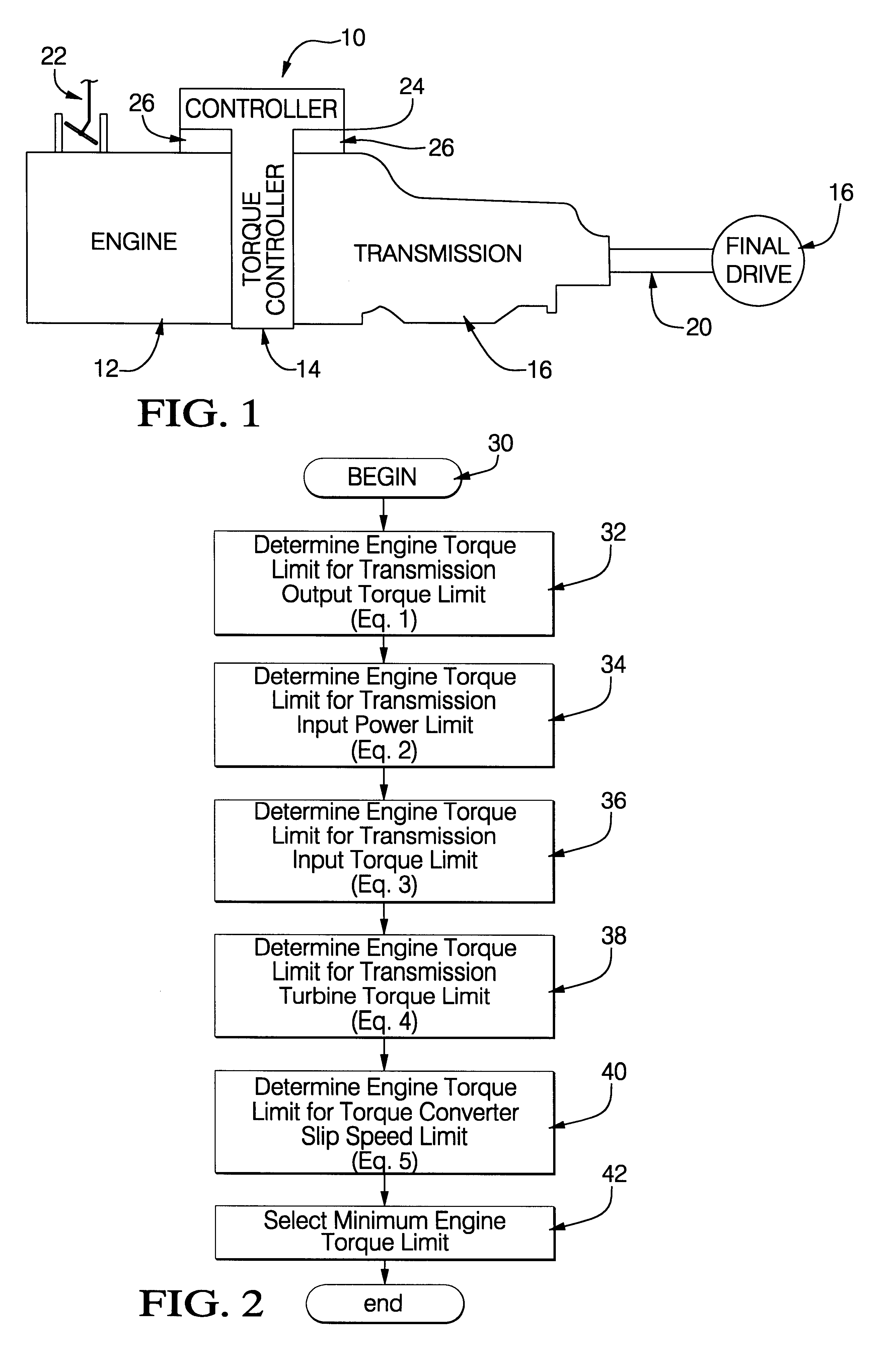
A powertrain 10, shown in FIG. 1, includes an engine 12, a torque converter 14, a multi-speed transmission 16, and a final drive 18. The engine 12 is a conventional internal combustion prime mover. The torque converter 14 is a conventional hydrodynamic mechanism. The transmission 16 is a conventional planetary gear mechanism that may be constructed in accordance with the gearing mechanism described in U.S. Pat. No. 4,070,927 issued Jan. 31, 1978. The transmission 16 preferably includes a conventional torque converter clutch that is engaged during vehicle operation to improve the fuel economy. The design and control of torque converter clutches is well-known to those skilled in the art. The final drive 18 is a conventional differential type gear mechanism, and is connected with the transmission 16 by a shaft 20. The powertrain may also include a conventional transfer gear mechanism, not shown, that would generally be located at the transmission output and divides the power flow betwe...


PUM


Abstract

A powertrain having a controller for limiting the torque and power inputs to a transmission as determined by operating parameters and design features of the transmission. These parameters and design features include torque limits for various components in the transmission, torque ratio of the torque converter, the design K factor of the torque converter, gear ratios of the transmission, operating condition of the torque converter clutch, and input power limits for the transmission. A programmable digital computer includes a subroutine that evaluates and establishes torque limits and input speed limits from the design features and operating parameter. The controller sets the limits for each transmission ratio including reverse such that a family of transmission can be coupled to a single engine design without overpowering the transmission should the engine be capable of greater output power than the transmission can accept.

Description

TECHNICAL FIELDThis invention relates to controlling the input power and torque to a multi-speed transmission in a powertrain.BACKGROUND OF THE INVENTIONPowertrains generally consist of an engine and a transmission. The transmission has a torque converter and a planetary gear arrangement which includes a plurality of torque transmitting mechanisms in the form of both rotating and stationary clutches and band brakes. Each of these elements as well as the shafts in the transmission have a maximum torque capacity which, if exceeded, may be detrimental to the operation of the powertrain. The torque converter has a stall torque point at which the maximum torque capacity is reached. Generally the engine and transmission are matched such that the engine output torque and the converter stall torque are compatible such that the maximum torque limit of the transmission input shaft is not surpassed.SUMMARY OF THE INVENTIONIt is an object of the present invention to provide an improved torque a...

Claims


Application Information

Patent Timeline
IPC IPC(8): F02D41/02
CPCF02D41/022F02D41/0225F02D2250/26Y10T477/679Y10T477/675Y10T477/68F02D2400/12
Inventor MC COLLUM ETCHASON, EDMONDKRESSE, JOHN PHUBBARD, GREGORY AROBINSON, TIMOTHY ALANRUNDE, JEFFREY KURT
Owner GM GLOBAL TECH OPERATIONS LLC
Features
  • Generate Ideas
  • Intellectual Property
  • Life Sciences
  • Materials
  • Tech Scout
  • Unparalleled Data Quality
  • Higher Quality Content
  • 60% Fewer Hallucinations
Learn More