Spinal cord removal tool

a technology for removing tools and spinal cords, applied in the field of tools, can solve problems such as affecting the operation of the tool and the proper affecting the removal of the spinal cord, and the fixed position of the side blade relative to the side edges of the removal blades

Inactive Publication Date: 2003-01-28
JARVIS PROD
View PDF6 Cites 5 Cited by
  • Summary
  • Abstract
  • Description
  • Claims
  • Application Information

AI Technical Summary

Benefits of technology

The blade disk spins between a left side blade and a right side blade. The side blades are mounted on the housing for motion towards and away from the left and right cutting edges of the spinal cord removal blades. A left side spring pushes the left side blade in towards the left cutting edges of the spinning spinal cord removal blades. A right side spring pushes the right side blade in towards the right cutting edges of the spinal cord removal blades. The floating spring mounting of the side blades makes them self-adjusting and ensures that they always remain in cutting contact with the side edges of the spinning removal blades.

Problems solved by technology

A related problem is the elongated spinal cord membrane, which tends to wrap around the shaft of motorized removal tools and interfere with operation of the tool and proper removal of the spinal cord.
One difficulty with the tool shown in EP 0 890 313 B1 is the fixed location of the side blades relative to the side edges of the removal blades.
As the blades wear, a gap quickly develops between these blades and the shearing action becomes intermittent.
The initial shaping of the blades by grinding is also very difficult in this design in view of the manner in which the side blades are non-adjustably mounted with a fixed spacing between them.

Method used


Image

  • Spinal cord removal tool
  • Spinal cord removal tool

Examples


Embodiment Construction

)

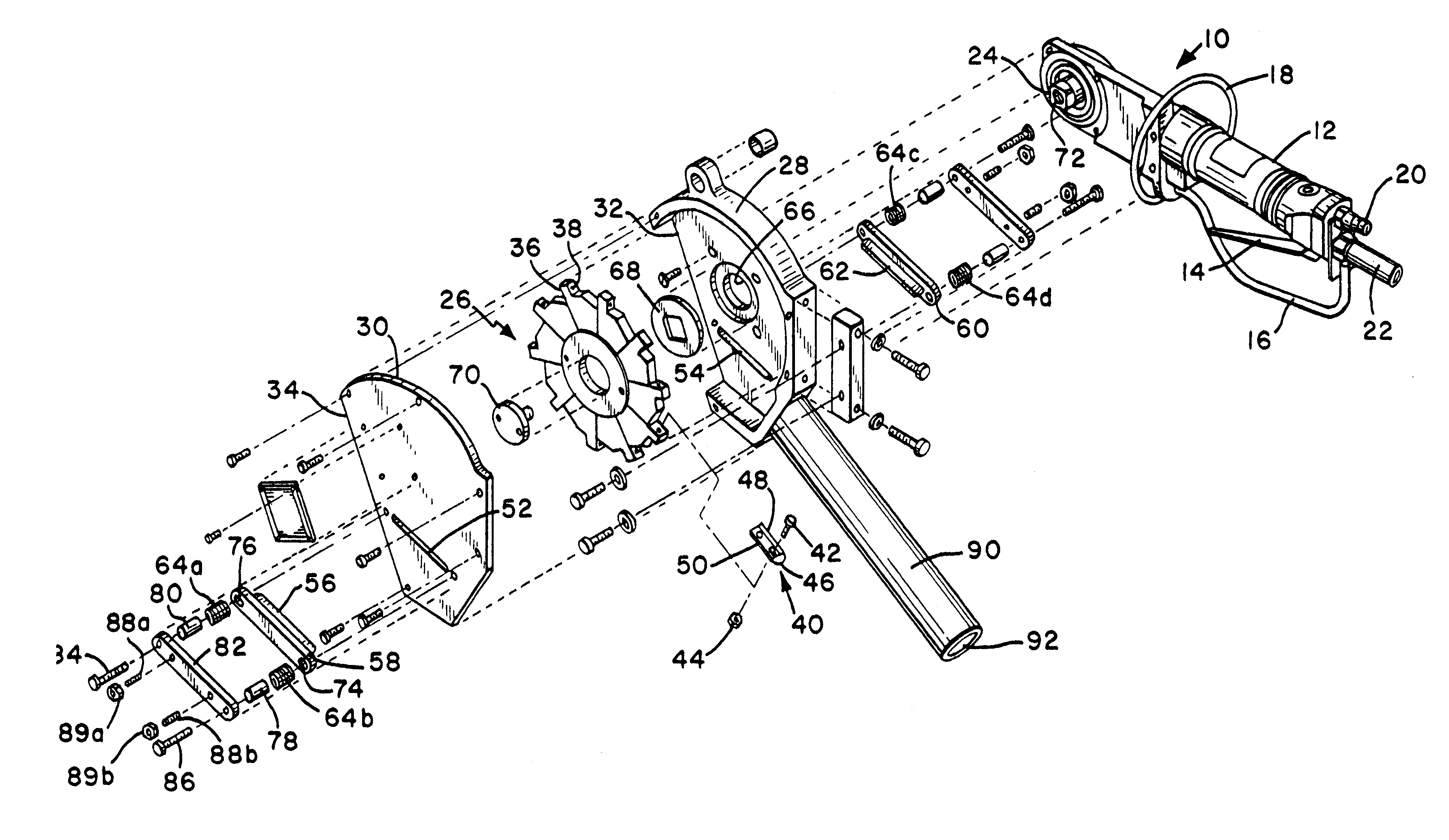
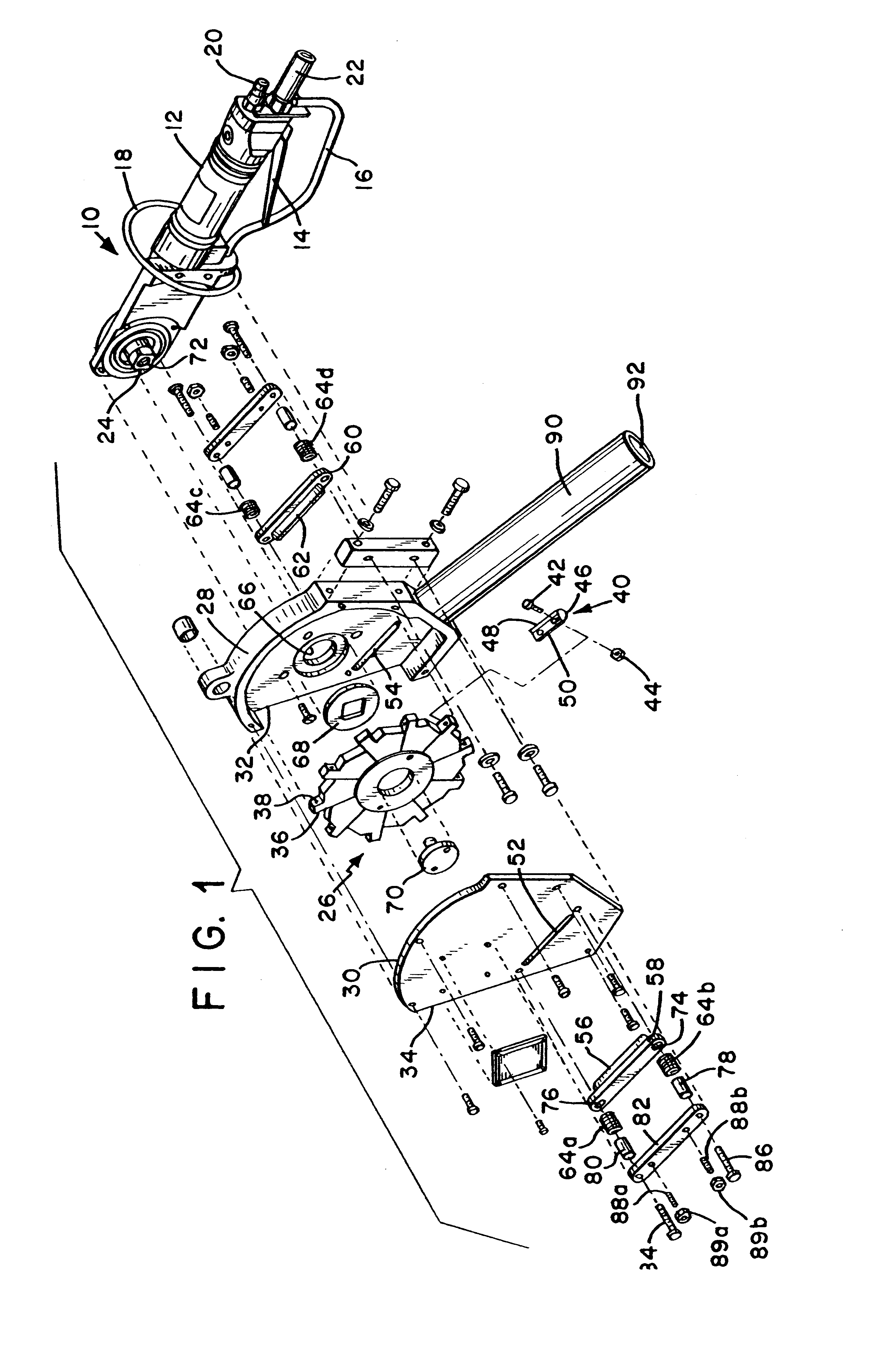
Referring to FIG. 1, the present invention includes a motor 10 having a handle 12, a trigger 14 for operating the tool and hand guards 16, 18. In the preferred embodiment, the motor 10 is a pneumatic motor connected to a supply of pressurized air via air inlet 20. Air is exhausted through exhaust outlet 22. In other embodiments, the motor may be an electric motor or the tool may be hydraulically powered, if desired.

When trigger 14 is actuated, the motor 10 spins square shaft 24, which drives the blade disk 26 in rotary motion inside of housing 28. Cover 30 forms a part of the housing so that the blade disk 26 is exposed only along a front working edge extending outward from edges 32 and 34 of the housing.

Square motor shaft 24 extends through opening 66 in housing 28, through washer 68 and into engagement with the blade disk 26. Cap screw 70 engages internal threads 72 in shaft 24 to hold the blade disk on the shaft 24.

Blade disk 26 is provided with multiple mounting surfaces 36 tha...


PUM


Abstract

A spinal cord removal tool for removing a spinal cord and spinal cord membrane from a carcass includes a spinning blade disk having multiple removal blades mounted around its perimeter, each removal blade having a forward facing cutting edge that can enter the spinal cord channel and side cutting edges that cooperate with floating self-adjusting side blades to chop the spinal cord membrane as it is brought into the tool.

Description

1. Field of the InventionThe present invention relates to tools for removing the spinal cord from carcasses.2. Description of Related ArtSpinal cord removal tools are used in the processing of carcasses to remove the spinal cord from the spinal cord channel surrounding it. Such tools may also be referred to as "spinal cord grinders" due to the difficulty of removing the spinal cord completely from the bony channel surrounding it, which has many irregularities and protrusions. A related problem is the elongated spinal cord membrane, which tends to wrap around the shaft of motorized removal tools and interfere with operation of the tool and proper removal of the spinal cord.One tool that addresses these problems in removing the spinal cord is seen in European Patent EP 0 890 313 B1, which uses a motor driven blade disk spinning inside a housing. The blade disk includes multiple spinal cord removal blades oriented perpendicular to the plane of the disk. The removal blades are spaced ar...

Claims


Application Information

Patent Timeline
Patent Type & Authority Patents(United States)
IPC IPC(8): A22B5/00
CPCA22B5/201A22B5/0005A61B17/56
Inventor GWYTHER, PETER
Owner JARVIS PROD
Why Eureka
Try Eureka