Motion detecting apparatus, motion detecting method, and storage medium storing motion detecting program for avoiding incorrect detection

Inactive Publication Date: 2003-01-28
SOVEREIGN PEAK VENTURES LLC
View PDF6 Cites 67 Cited by
  • Summary
  • Abstract
  • Description
  • Claims
  • Application Information

AI Technical Summary

Benefits of technology

With this construction, when luminance greatly changes in a fairly short time due to light flash or strong flicker, the mistake of detecting a flat area (such as a wall or a floor where luminance is relatively even) can be avoided.
In addition, the second judging unit judges the present block as a motion block when a direction and magnitude of a motion vector of the present block are roughly similar to motion vectors of blocks surrounding the present block. Accordingly, it is possible to avoid the mistake of detecting the flat area under circumstances where luminance greatly changes due to light flash or strong flicker.

Problems solved by technology

However, this method is problematic as it requires the security personnel to constantly watch the surveillance cameras long hours.

Method used


Image

  • Motion detecting apparatus, motion detecting method, and storage medium storing motion detecting program for avoiding incorrect detection
  • Motion detecting apparatus, motion detecting method, and storage medium storing motion detecting program for avoiding incorrect detection
  • Motion detecting apparatus, motion detecting method, and storage medium storing motion detecting program for avoiding incorrect detection

Examples


first embodiment

The following is a description of a motion detecting apparatus of the first embodiment of the present invention with reference to figures.

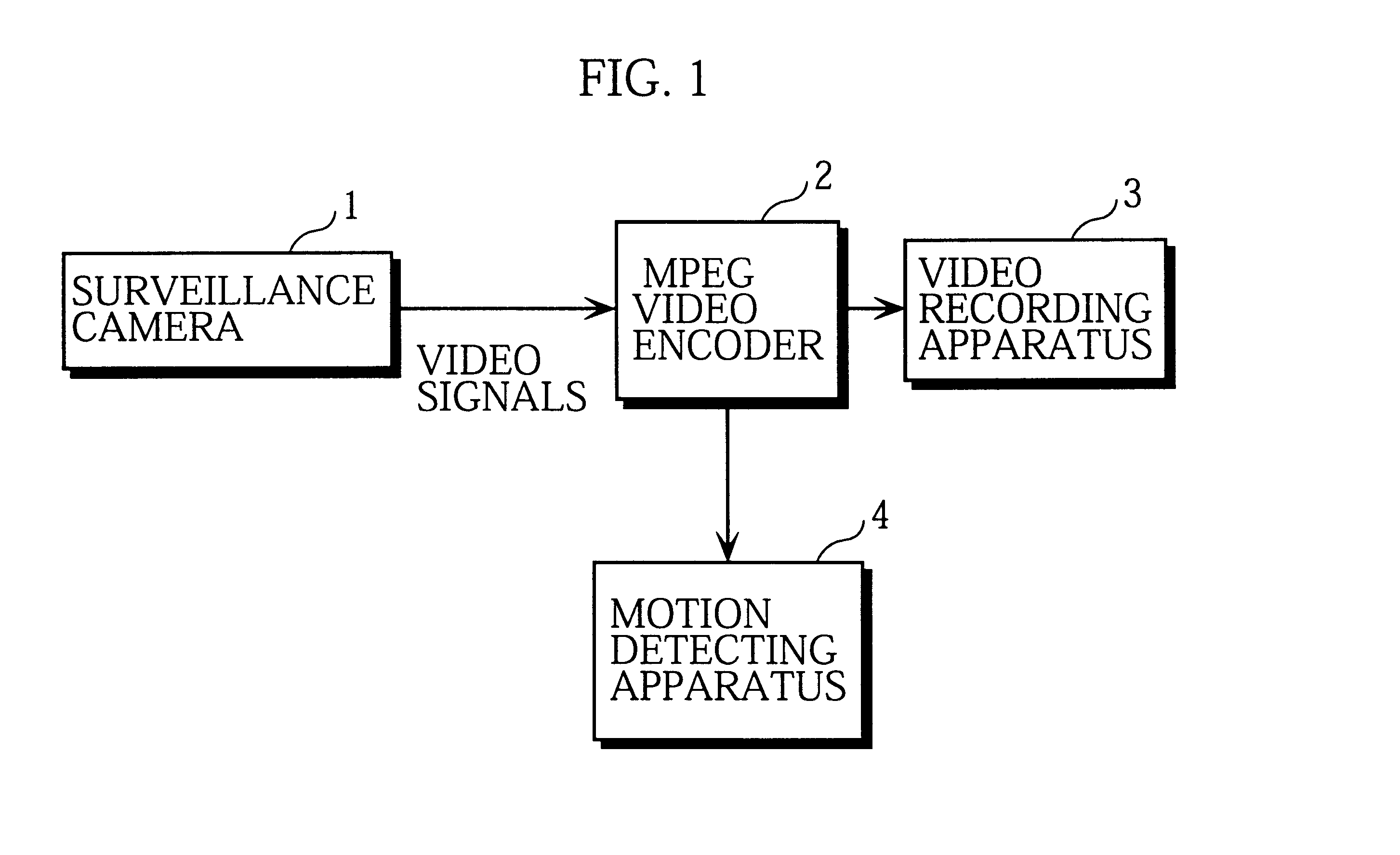
FIG. 1 is a block diagram showing the general configuration of a motion detecting system that includes a motion detecting apparatus and its peripheral apparatuses.

In the figure, the motion detecting system is roughly made up of a surveillance camera 1, a MPEG video encoder 2, a video recording apparatus 3, and a motion detecting apparatus 4.

The surveillance camera 1 outputs video signals of taken images to the MPEG video encoder 2.

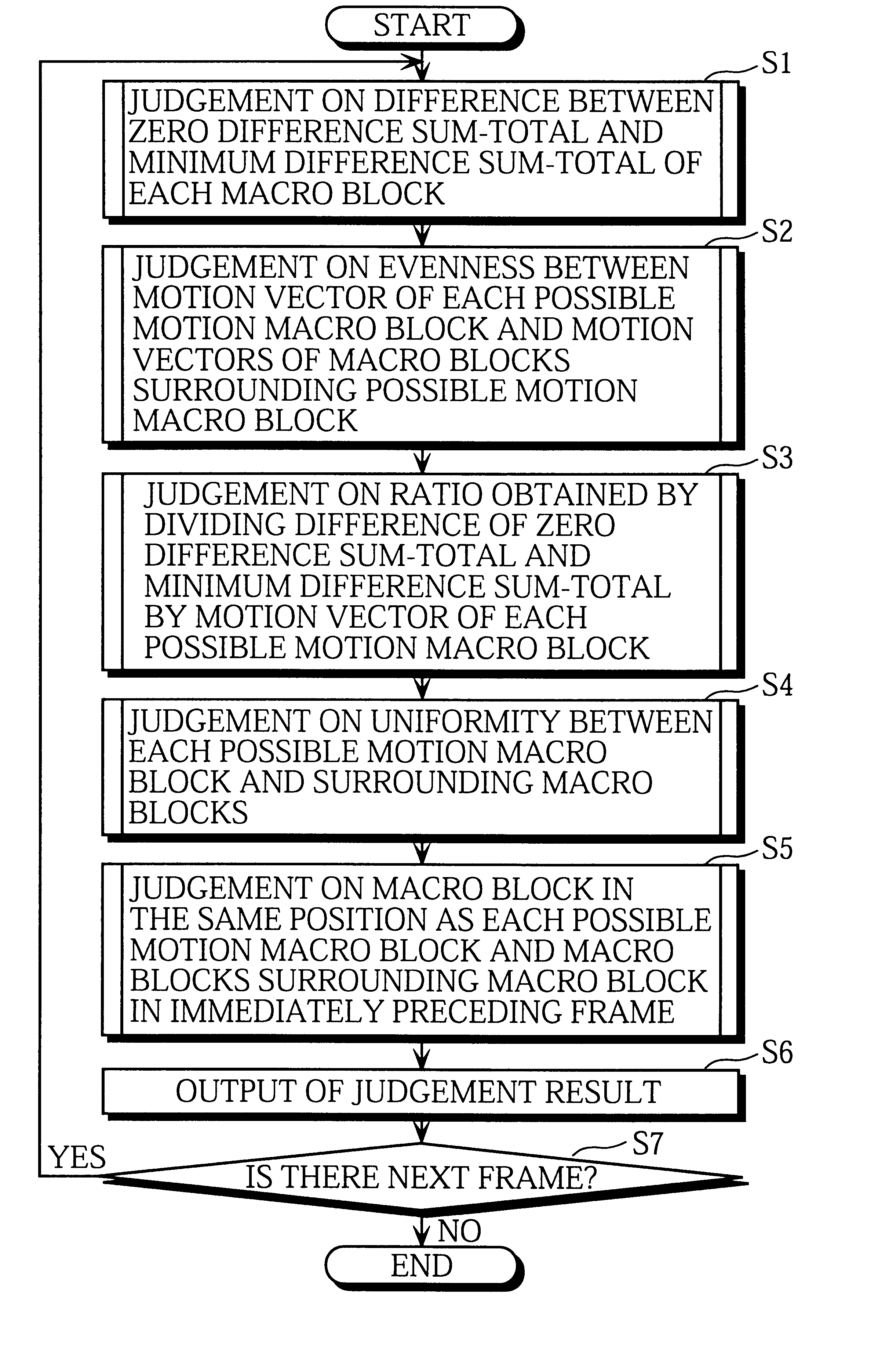
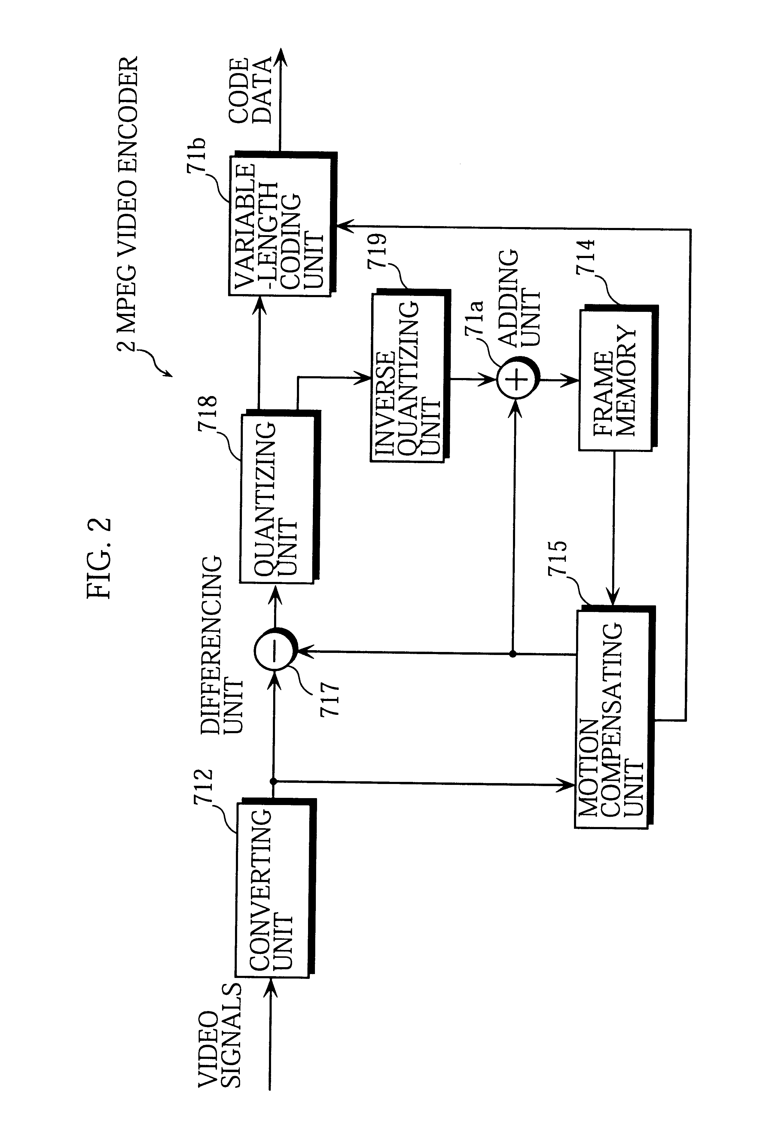
The MPEG video encoder 2 codes the video signals according to the MPEG and outputs coded data to the video recording apparatus 3. The MPEG video encoder 2 also outputs zero difference sum-totals, minimum difference sum-totals, and motion vectors calculated during the coding to the motion detecting apparatus 4. The terms mentioned here are explained later with the construction-of the MPEG video encoder 2.

The video recordi...

second embodiment

A motion detecting apparatus of the second embodiment of the present invention includes a RAM that prestores a critical area and a critical direction set on a frame. When one or more motion macro blocks detected as a result of the motion detection processing are present within the critical area and an average direction of motion vectors of the motion macro blocks is approximately the same as the critical direction, the motion detecting apparatus generates an alarm.

This motion detecting apparatus is explained below with reference to figures.

FIG. 13 is a block diagram showing the construction of the motion detecting apparatus 13 of the second embodiment.

In the figure, the motion detecting apparatus 13 is roughly made up of a CPU 131, a RAM 132, an alarm generating device 133, a ROM 134, and the I / O interface 9. Note here that construction elements which are the same as those in the first embodiment in FIG. 3 have been given the same reference numerals and their explanation has been om...


PUM


Abstract

To provide a motion detecting apparatus that judges whether each macro block shows a part of an object in motion using motion vectors calculated by a general-purpose MPEG video encoder during motion compensation. The motion detecting apparatus compares a motion vector of a present macro block with motion vectors of macro blocks surrounding the present macro block. If the motion vector of the present macro block and the motion vectors of the surrounding macro blocks are not random in direction and magnitude, the motion detecting apparatus judges that the present macro block shows a part of an object in motion. Otherwise, the motion detecting apparatus judges that the present macro block does not show a part of an object in motion.

Description

1. Field of the InventionThe present invention relates to a motion detecting apparatus, a motion detecting method, and a storage medium storing a motion detecting program for detecting motion of objects using motion vectors obtained by a MPEG video encoder.2. Description of the Prior ArtWith extension of business hours in stores and increase in the number of unattended facilities, the demand for reinforcing crime prevention measures in such stores and facilities is growing these days. As a representative measure, one or more surveillance cameras are placed in a store so that the security personnel can monitor images taken by the cameras.However, this method is problematic as it requires the security personnel to constantly watch the surveillance cameras long hours. To lessen the workload for the security personnel, a conventional motion detecting apparatus is used for detecting motion of objects such as persons in images taken by a surveillance camera. When motion is detected on the...

Claims


Application Information

Patent Timeline
Patent Type & Authority Patents(United States)
IPC IPC(8): G08B13/194H04N5/14
CPCG08B13/19602G08B13/19606H04N19/139H04N5/145H04N19/503G08B13/19667
Inventor SHIMIZU, KAZUHITOINOUE, SHUJI
Owner SOVEREIGN PEAK VENTURES LLC
Why Eureka
Try Eureka