Heat conditioning process

Inactive Publication Date: 2003-02-04
OERLIKON SOLAR AG (TRUEBBACH)
View PDF9 Cites 8 Cited by
  • Summary
  • Abstract
  • Description
  • Claims
  • Application Information

AI Technical Summary

Problems solved by technology

Thereby, considerable time lapses, until the substrates reach the final desired temperature.
Thereby it must be emphasised that thermal gradients in the substrate would lead to different magnitude expans

Method used


Image

  • Heat conditioning process
  • Heat conditioning process
  • Heat conditioning process

Examples


Example

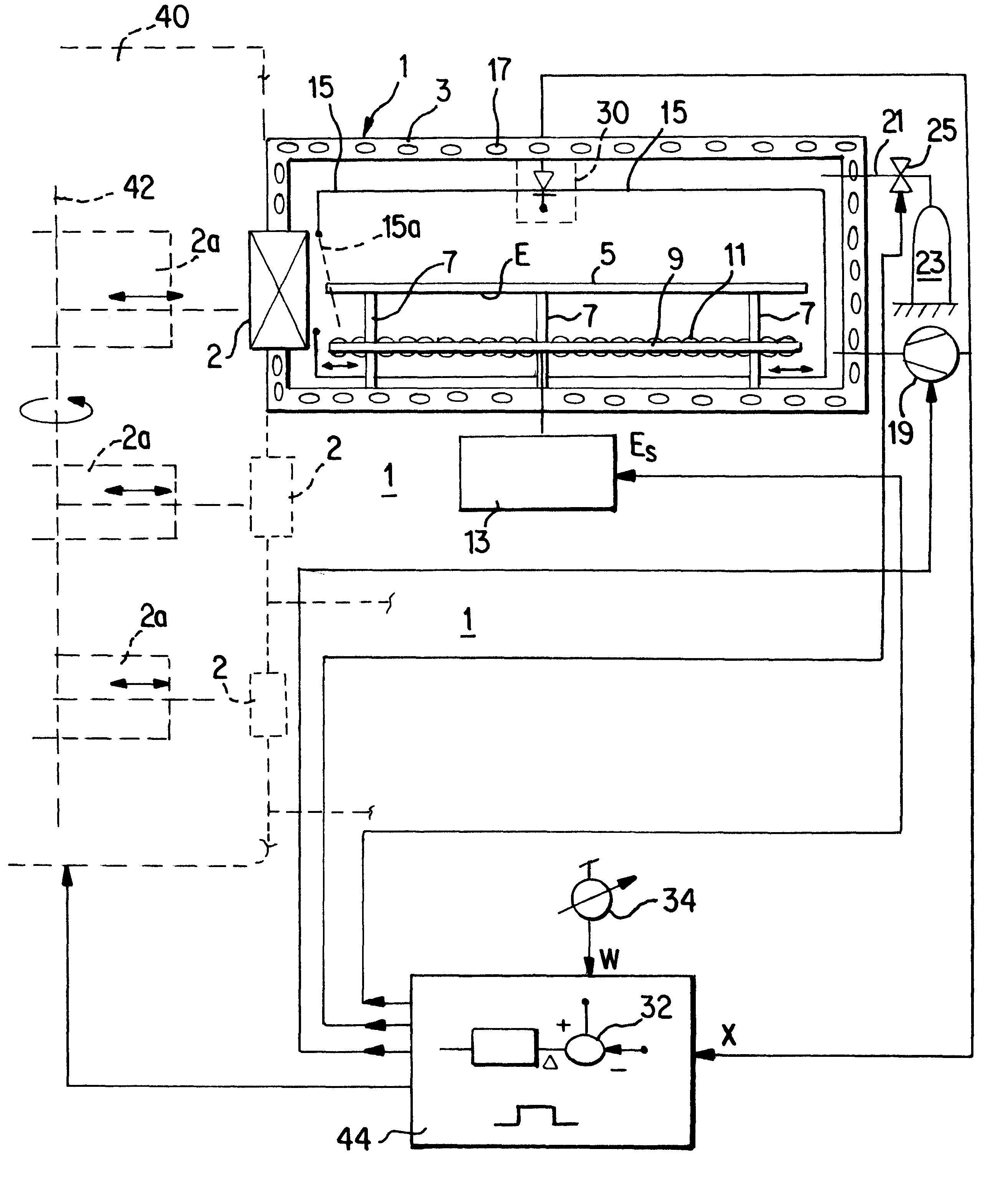
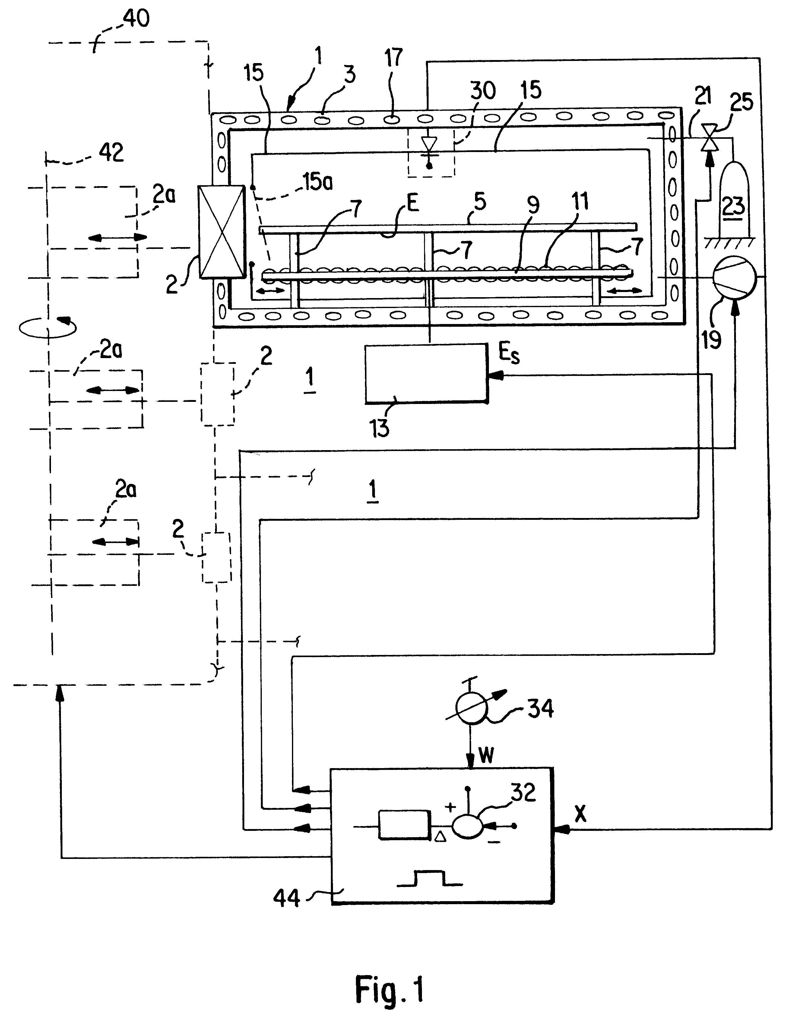
According to FIG. 1 an inventive heating vacuum chamber 1 comprises a surrounding rigid wall 3 defining in the preferred form as shown for a flat box-shaped or drawer-shaped chamber. The interior of the chamber 1 is accessible for feeding and removing a glass substrate 5 via an input / output lock as e.g. realised by a slot valve.

The substrate 5 is deposited within chamber 1 on a holder arrangement which is formed by a predetermined number of pins 7, according to the size of the substrate 5, which pins are of a thermically resistant, thermically isolating material, as of a polymer material. As will be later explained, the holder arrangement and especially the pins 7 are provided with a reflective outer layer, the characteristics of the reflecting layer as especially of Aluminum being substantially equal to that of a reflecting arrangement as previously described.

Beneath the deposition plane E for the substrate 5, as defined by the pins 7, there is mounted in the chamber a lamp holder ...


PUM

PropertyMeasurementUnit
Fractionaaaaaaaaaa
Fractionaaaaaaaaaa
Fractionaaaaaaaaaa

Abstract

For heat conditioning flat panel glass substrates the substrates are directly exposed in vacuum to the radiation of lamps, the lamps being selected so that their spectral radiation characteristics (b, c) fit with the absorption characteristics (a) of the glass of the substrate.

Description

The present invention is directed to a technique for heat conditioning glass substrates, which are subsequently surface treated by vacuum surface treatment. The invention departs from requirements which are encountered when large glass substrates for display panel production from 300 cm.sup.2 up to 1 m.sup.2 and more have to be heat conditioned.PRIOR ARTFor subsequent vacuum coating surfaces of glass substrates in the flat panel industry, as by aluminum sputtering, water molecules must previously have been removed from the surface of the substrate. This is customarily performed by heating which additionally degases and cleans the surfaces from further surface contaminations.To perform such heat conditioning it is known to convey a multitude of substrates into an oven which is heated e.g. up to 250.degree. C. The oven is operated at vacuum atmosphere. Thereby, considerable time lapses, until the substrates reach the final desired temperature. So as not to deteriorate the high through...

Claims


Application Information

Patent Timeline
IPC IPC(8): C03C17/00C03C23/00C03B32/00
CPCC03C23/007C03C17/002
Inventor DESCHAMPS, ARNAUDMUELLER, WILLIRHYNER, STEPHANGALDOS, AITOR
Owner OERLIKON SOLAR AG (TRUEBBACH)
Why Eureka
Try Eureka