High capacity multiple-stage railway switching yard

a switching yard and high-capacity technology, applied in railway stations, railway hauling devices, ways, etc., can solve the problems of limiting the maximum throughput of the yard, single-stage yards often cannot create as many blocks as are needed, and no "second chance" to adjust the arrangement of cars

Inactive Publication Date: 2003-02-11
KRAFT EDWIN R
View PDF22 Cites 113 Cited by
  • Summary
  • Abstract
  • Description
  • Claims
  • Application Information

AI Technical Summary

Problems solved by technology

The problem is that it is a rigid Henry Ford, 1920's-style assembly line, rather than adapting yard design to current just-in-time manufacturing paradigms--which emphasize flexibility, short setup times and rapid response to changing and always unpredictable customer needs.
(a) make connections as scheduled,
(b) protect capacity on outbound trains needed for higher priority cars,
(c) accommodate "block swapping" or
(d) benefit from switching already done at a previous yard.
Single stage sorting is very restrictive, since it limits the number of classifications or "blocks" that can be built to no more than the number of tracks in the yard, and once cars are classified, affords no "second chance" to adjust the arrangement of cars.
Even if a yard is built with many short tracks, single stage yards often cannot create as many blocks as are needed.
Usually this "flat" switching operation, and not the sorting capacity of the hump, limits maximum throughput of the yard.
This need for high capacity has been recognized for a long time, in fact, a lack of sufficient capacity using traditional gravity sorting has been thought to render multiple stage switching infeasible.
It may never have been proposed before because it would be inoperative using the sorting techniques presently employed by railroads.
The main weakness of the yard shown in FIG. 10 of the parent application is that it only allows one train to be processed at a time.
(a) It becomes necessary to coordinate processing activities of two humps at both ends of the yard, since cars cannot be safely humped into a track from both directions simultaneously.
(b) Double ended designs cause difficulties in establishing proper gradients throughout the length of the yard. Cars would tend to collect at the low point of the yard in the middle, rather than rolling all the way to the ends of the tracks. This problem could be overcome, at some cost, by employing booster units (an optional feature of the "Dowty" retarder system) to keep the cars rolling.
(c) Humps 90a and 90b on both ends of the yard block access to classification tracks 55 needed by arriving and departing trains, and also prevent flat switching. Although the lapped design as in FIG. 15 of the parent application partially addresses the problem, a fully open arrival / departure end 80 as shown in FIG. 10 of the parent application is even more desirable to minimize interference with hump 90 operations.
(d) Finally, sorting activity in a double-ended yard may become so intense as to render impractical the inspection and repair of cars while they lie in the classification tracks. This defeats one of the main benefits of multiple stage switching, which is the ability to effectively utilize car time waiting for connections to perform maintenance and other mechanical servicing activities.
Although double hump leads with crossovers are often provided in single stage yards, they are of limited value since parallel hump operations frequently interfere with one another.

Method used


Image

  • High capacity multiple-stage railway switching yard
  • High capacity multiple-stage railway switching yard
  • High capacity multiple-stage railway switching yard

Examples


embodiment

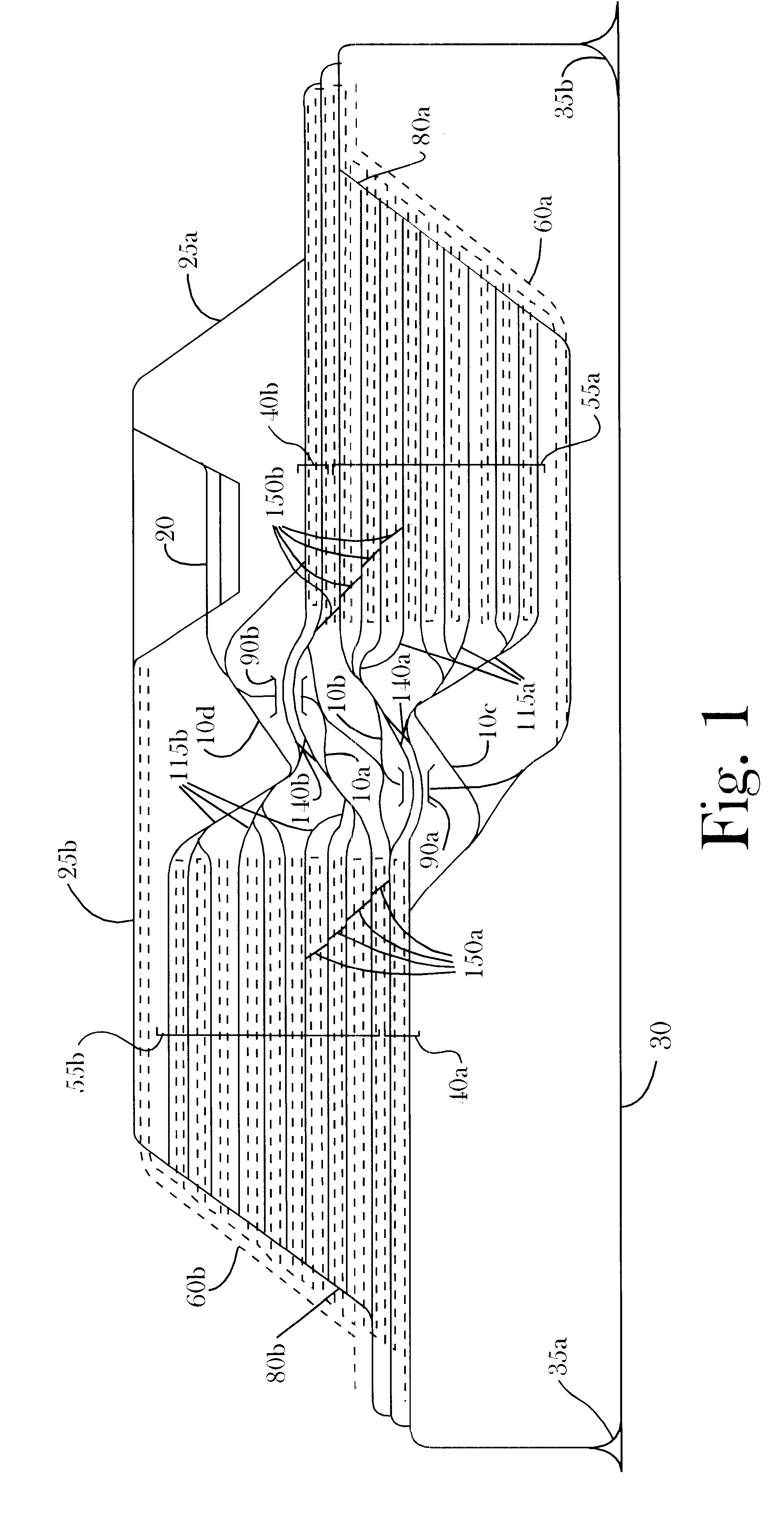
FIG. 3--Alternative Embodiment

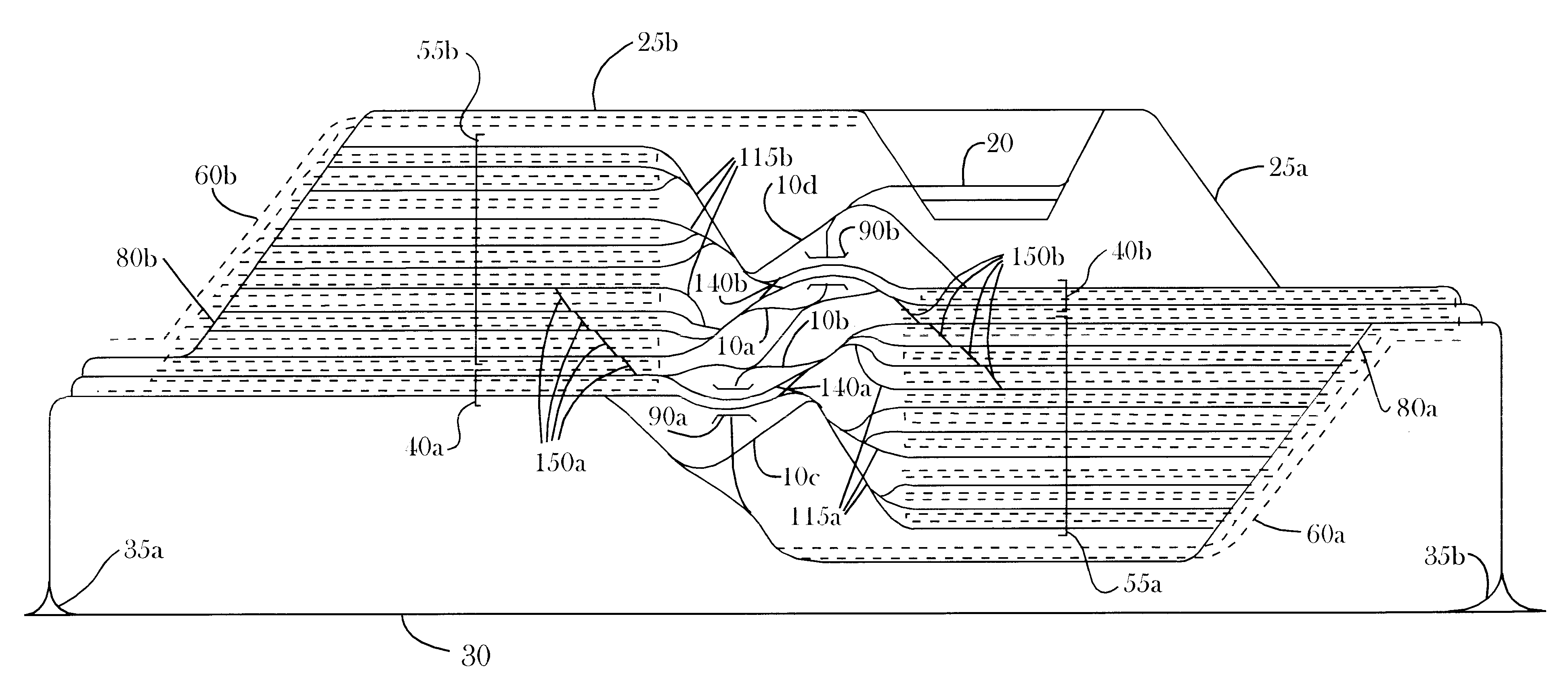
An alternative embodiment consists of the yard of FIG. 3, operated by the method of partial preblocking of cars to bypass the first stage sort. In FIG. 3, a double hump lead with scizzors crossovers 140 has been added to the yard of FIG. 10 in the parent application, to allow parallel humping to proceed concurrently during the second stage sort. If adequate preblocking support can be provided, the yard of FIG. 3 could handle as much traffic as a large conventional single-stage yard, without needing the second sub-yard as shown in FIG. 1.

The best yard design for any given locale depends on the number of cars needing to be switched, land availability and cost, and the degree to which surrounding yards are able to provide preblocking support. However as a rule, the simplest design capable of providing the required capacity should be chosen. The more complicated design of FIG. 1 should be introduced only when the simpler yard of FIG. 3 is unable to handle t...


PUM


Abstract

A high capacity, multiple-stage railway car switching yard connects together two or more subyards. Each subyard has a fully open arrival / departure end and may have a continuously descending gradient throughout the entire length of its classification tracks. The subyards are positioned opposite one another, so classification tracks of one subyard can serve as receiving tracks for another subyard. Escape tracks are interconnected between the two subyards to provide a higher capacity and more efficiency and flexibility than a single yard by itself.

Description

This invention relates to railroads, particularly to methods of sorting cars in railroad yards.DESCRIPTION OF THE RELATED ARTCopending utility patent application Priority Car Soiling In Railroad Classification Yards Using a Continuous Multi-Stage Method by Edwin R. Kraft, Ser. No. 09 / 716,300 (hereinafter referred to as the "parent application") describes new methods of multiple stage sorting in railroad classification yards. It also suggests several new yard designs to maximize the effectiveness of those methods. An extensive review of prior art is also included in the parent application. Further refinements to those operating methods and yard designs are disclosed herein.Copending U.S. application Ser. No. 09 / 716,300 is incorporated by reference into this application, as provided by Manual of Patent Examining Procedure, Section 608.01(p). However, some repetition of material already covered in the parent application is necessary. In cases where drawing figures or tables from the pa...

Claims


Application Information

Patent Timeline
Patent Type & Authority Patents(United States)
IPC IPC(8): B61B1/00B61L17/00
CPCB61L17/00B61B1/005
Inventor KRAFT, EDWIN R.
Owner KRAFT EDWIN R
Why Eureka
Try Eureka