Fuel injection system for marine engine

a fuel injection system and engine technology, applied in the direction of liquid fuel feeders, machines/engines, crankcase compression engine lubrication, etc., can solve the problems of water entering the tank and mixing with fuel, water within the fuel injection system tending to damage the system, and the damage to the fuel injectors by salt water in the fuel supply is particularly detrimental to the effect of salt water in the fuel supply

Inactive Publication Date: 2003-02-11
SANSHIN KOGYO CO LTD
View PDF26 Cites 21 Cited by
  • Summary
  • Abstract
  • Description
  • Claims
  • Application Information

AI Technical Summary

Problems solved by technology

The user or operator thus fills the tank with fuel under the conditions that present the possibility of water entering the tank and mixing with the fuel.
Water within the fuel injection system tends to damage the system, especially if salt water is introduced into the system.
The damaging effects of salt water in the fuel supply is particularly detrimental to the fuel injectors.
Fuel injectors are extremely precise and delicate, and do not function properly once rusted.
If the fuel injected into the combustion chambers contains too much lubricant, however, lubricant is not only wasted, but it also produces white smoke in the exhaust gases and fouls the spark plugs of the engine, i.e., the spark plugs fail to spark due to deposits, which the lubricant likely produces, on their electrodes.

Method used


Image

  • Fuel injection system for marine engine
  • Fuel injection system for marine engine
  • Fuel injection system for marine engine

Examples


Embodiment Construction

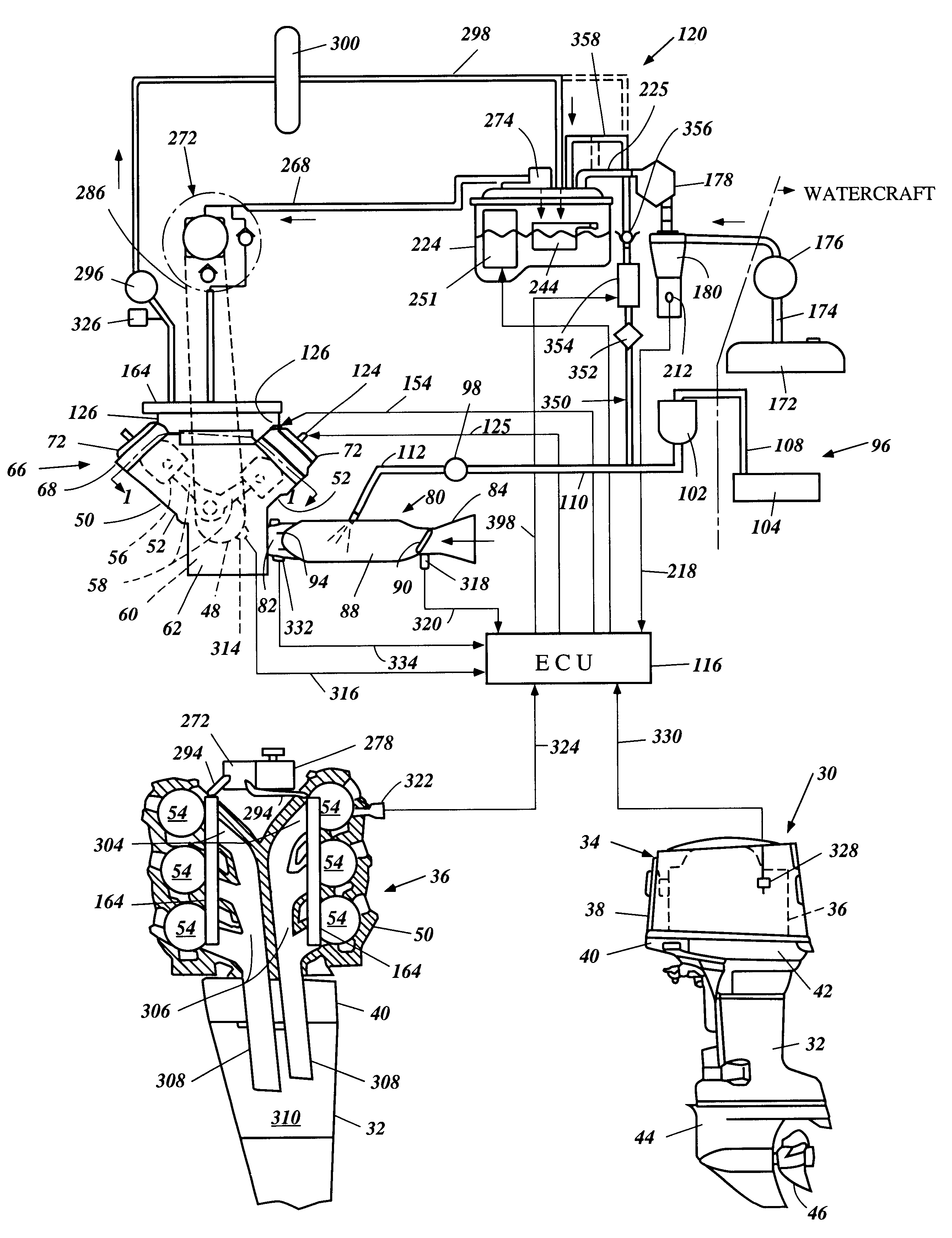
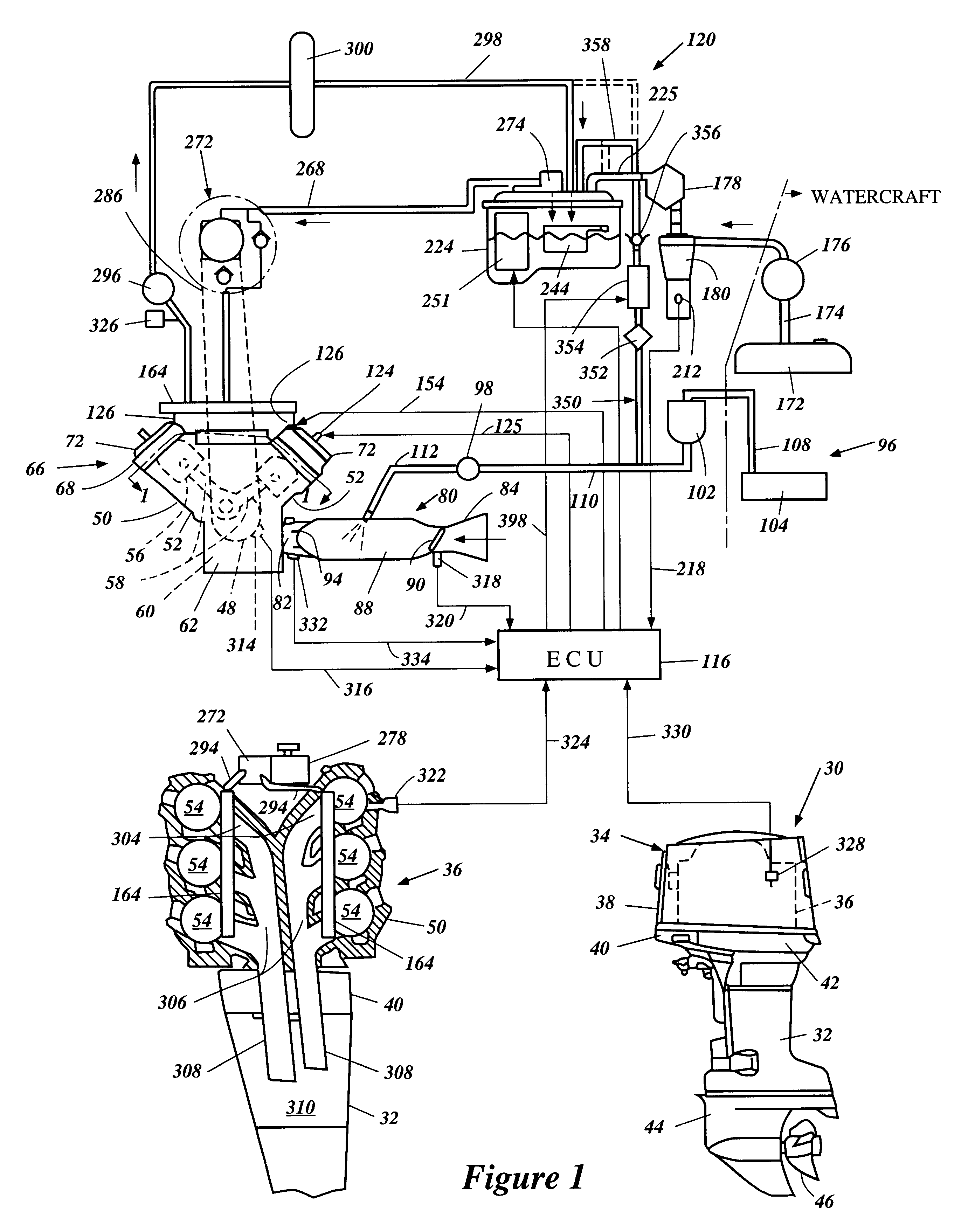
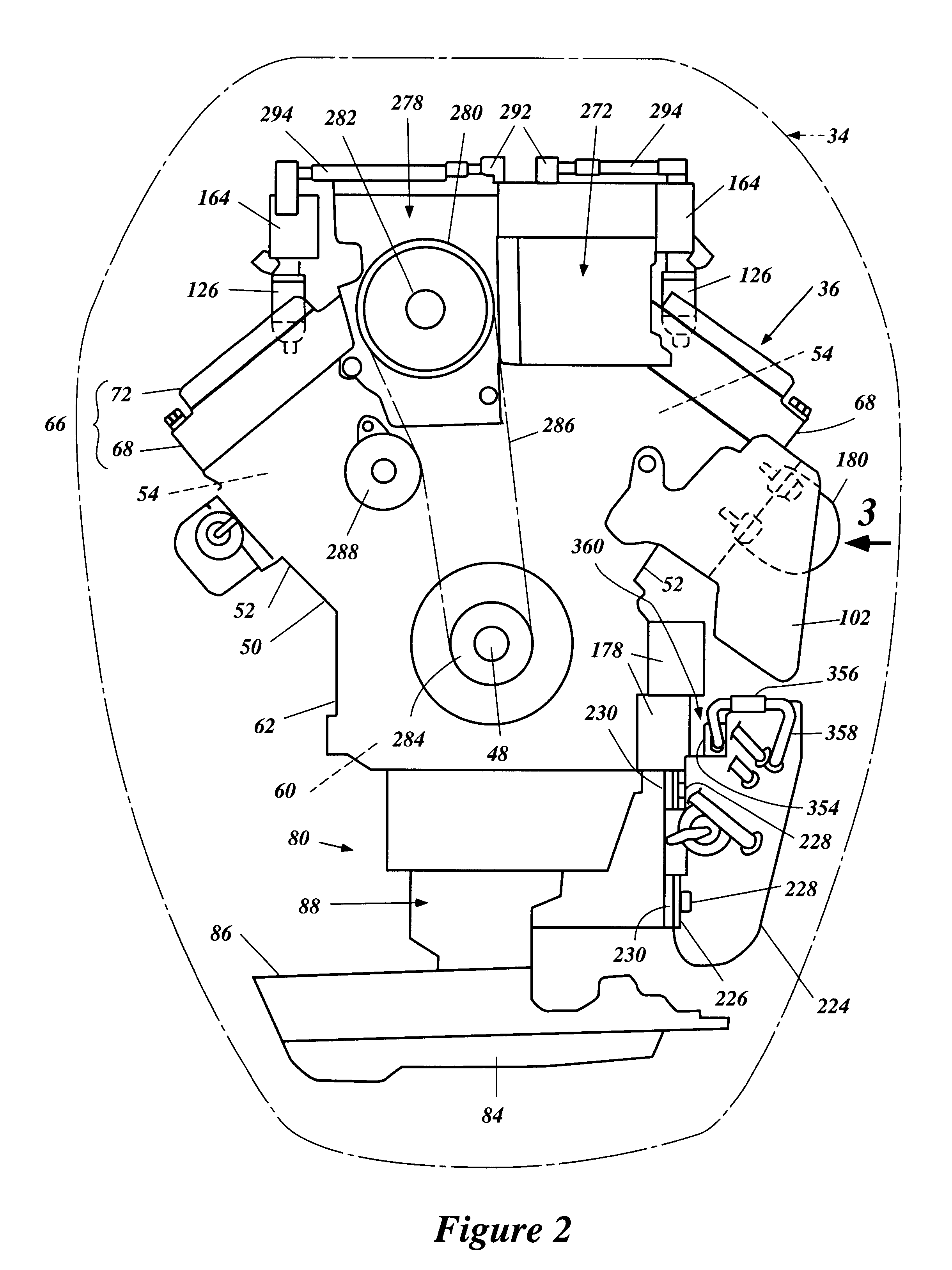
An exemplifying environment in which the present invention can be practiced will now be described with reference to FIGS. 1 to 7. The present fuel injection system has particular utility in the context of a marine engine, and thus, is described in the context of an outboard motor. The fuel injection system, however, can be used with other types of internal combustion engines employed in an environment in which the possibility of water entering the fuel supply system exists, e.g., with an engine driving a dredging pump.

With initial reference to FIG. 1, and in particular to the lower-right hand view of FIG. 1, an outboard motor 30 is depicted from the side. The entire outboard motor 30 is not depicted in that a swivel bracket and a clamping bracket, which are typically associated with a driveshaft housing 32, are not illustrated. These components are well known in the art and the specific method by which the outboard motor 30 is mounted to the transom of an associated watercraft is no...


PUM


Abstract

A fuel injection system for a marine engine includes an improved construction that, by the introduction of lubricant into the fuel, inhibits components of the system from rusting in the event that water, particularly salt water, is mixed with the fuel. The engine includes a lubricant delivery system to deliver lubricant to at least one portion of the engine that needs lubrication. A premix lubricant pump is provided for supplying lubricant with the fuel injection device from the lubricant delivery system so as to mix the part of the lubricant to the fuel. An ECU controls an amount of the part of the lubricant so as to be in a proper and extremely small range.

Description

PRIORITY INFORMATIONThis application is based on and claims priority to Japanese Patent Applications No. 11-162559, filed Jun. 9, 1999, No. 11-165708, filed Jun. 11, 1999 and No. 11-173957, filed Jun. 21, 1999, the entire contents of which are hereby expressly incorporated by reference.1. Field of the InventionThis invention relates to a fuel injection system for a marine engine, and more particularly to an improved fuel injection system with corrosion protection.2. Description of Related ArtIn all fields of engine design, there is an increasing emphasis on obtaining more effective emission control, better fuel economy and, at the same time, continuing to increase power output. This trend has resulted in the substitution of fuel injection systems for carburetors as the engine charge former.Fuel injection systems typically inject fuel into the air intake manifold. In addition, direct injection systems are being considered to obtain still better engine performance. The direct fuel inj...

Claims


Application Information

Patent Timeline
Patent Type & Authority Patents(United States)
IPC IPC(8): F02M61/16F01M3/02F02M69/10F02M61/00F02B75/00F01M3/00F02B33/04F02B75/22F02B33/02F02B61/00F02B61/04F02M51/06F02B75/18
CPCF01M3/02F02B33/04F02B61/045F02M69/10F02M51/0664F02M61/162F02B75/22F02B2075/1824
Inventor KATO, MASAHIKOTAKASE, HIROAKI
Owner SANSHIN KOGYO CO LTD
Why Eureka
Try Eureka