Equipment rack with integral HVAC and power distribution features

a technology of equipment racks and features, applied in the direction of electrical apparatus contruction details, dismountable cabinets, movable shelves, etc., can solve the problems of inconvenient use of prior art racks, inconvenient cooling of equipment, and the size of data center processing equipment, etc., to improve cooling and power distribution, simplify power distribution

Inactive Publication Date: 2003-02-11
SERVER ACQUISITION CORP
View PDF29 Cites 62 Cited by
  • Summary
  • Abstract
  • Description
  • Claims
  • Application Information

AI Technical Summary

Benefits of technology

Thus, a need exists for an improved racking system that improves cooling and power distribution for equipment mounted therein. The present invention addressed this need by providing a racking system that allows for even distribution of cool air to all equipment without the need for intrusive duct-work or other common spot-cooling solutions by combining the rack and HVAC ducting footprint into the footprint previously occupied by only the conventional rack mounting system. The racking system of the present invention also simplifies power distribution between the equipment in a rack and between adjacent racks.

Problems solved by technology

Data center processing equipment has been getting smaller over the years.
There are several problems associate with the use of EIA-spec telecommunications racks, and other similar racks.
However, the design of typical racks and cabinets do not facilitate easy cooling of the equipment when densely mounted in rack or cabinets.
While racks with integral cooling ducts have been provided in the past for certain application, such prior art racks have not been suitable or convenient for use in communications facilities having a large number of pieces of 1U equipment or the like.
In addition, such prior art racks have not facilitated easy, efficient and convenient power distribution between various pieces of equipment and between various racks.
As a result, power cables and the like are often not provided in a neat, orderly and secure fashion and, as a result, accidental power loss can result.
It is very difficult to distribute cool air effectively to all of the equipment in a densely populated data center.
It is also difficult to distribute power to all of the equipment in a neat, orderly and efficient manner.

Method used


Image

  • Equipment rack with integral HVAC and power distribution features
  • Equipment rack with integral HVAC and power distribution features
  • Equipment rack with integral HVAC and power distribution features

Examples


Embodiment Construction

The preferred embodiment of the instant invention will now be described with reference to the appended drawings. The preferred embodiments described herein and shown in the drawings are only exemplary and are not meant to limit the invention to the specific form and configuration thereof other than as set forth in the claims.

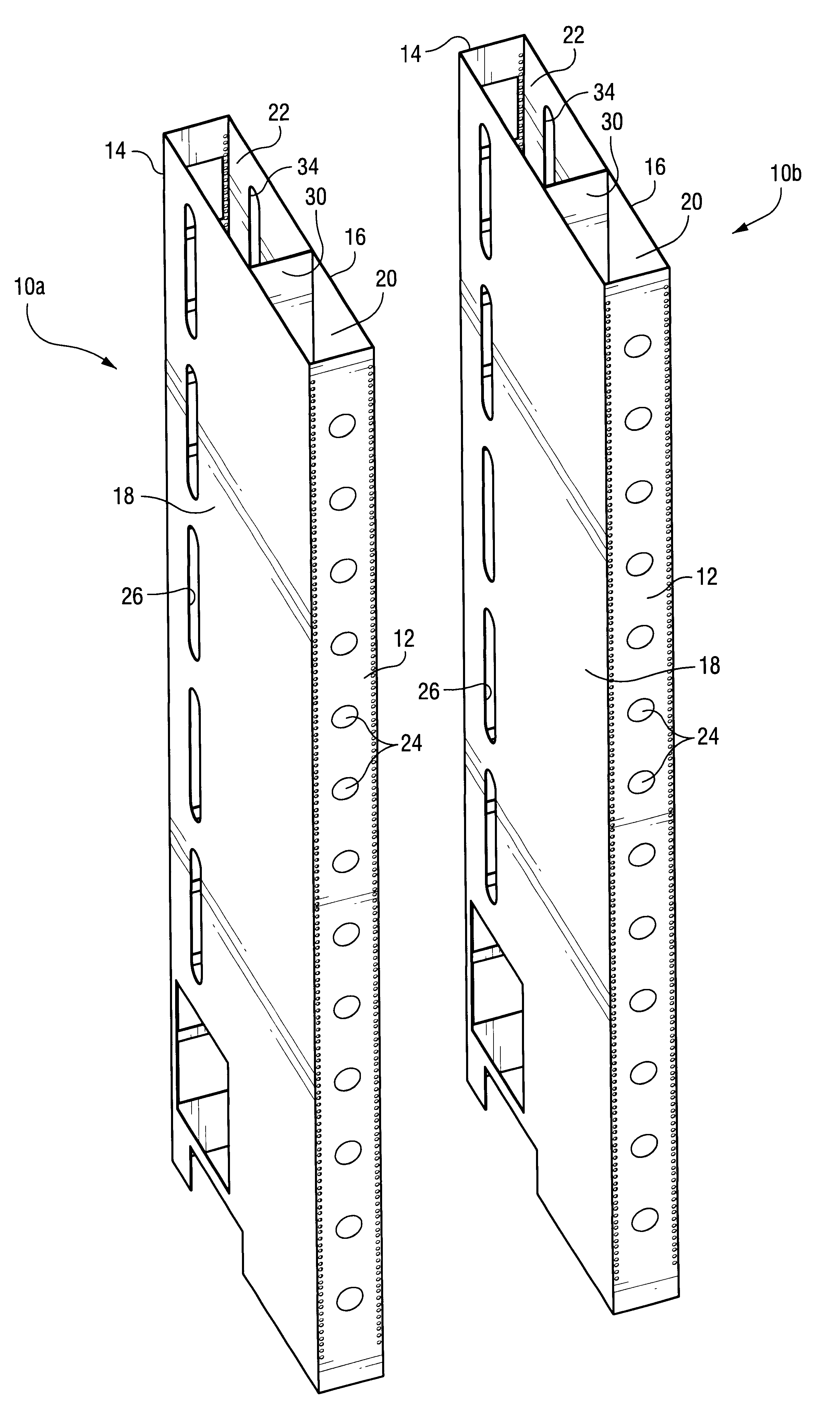
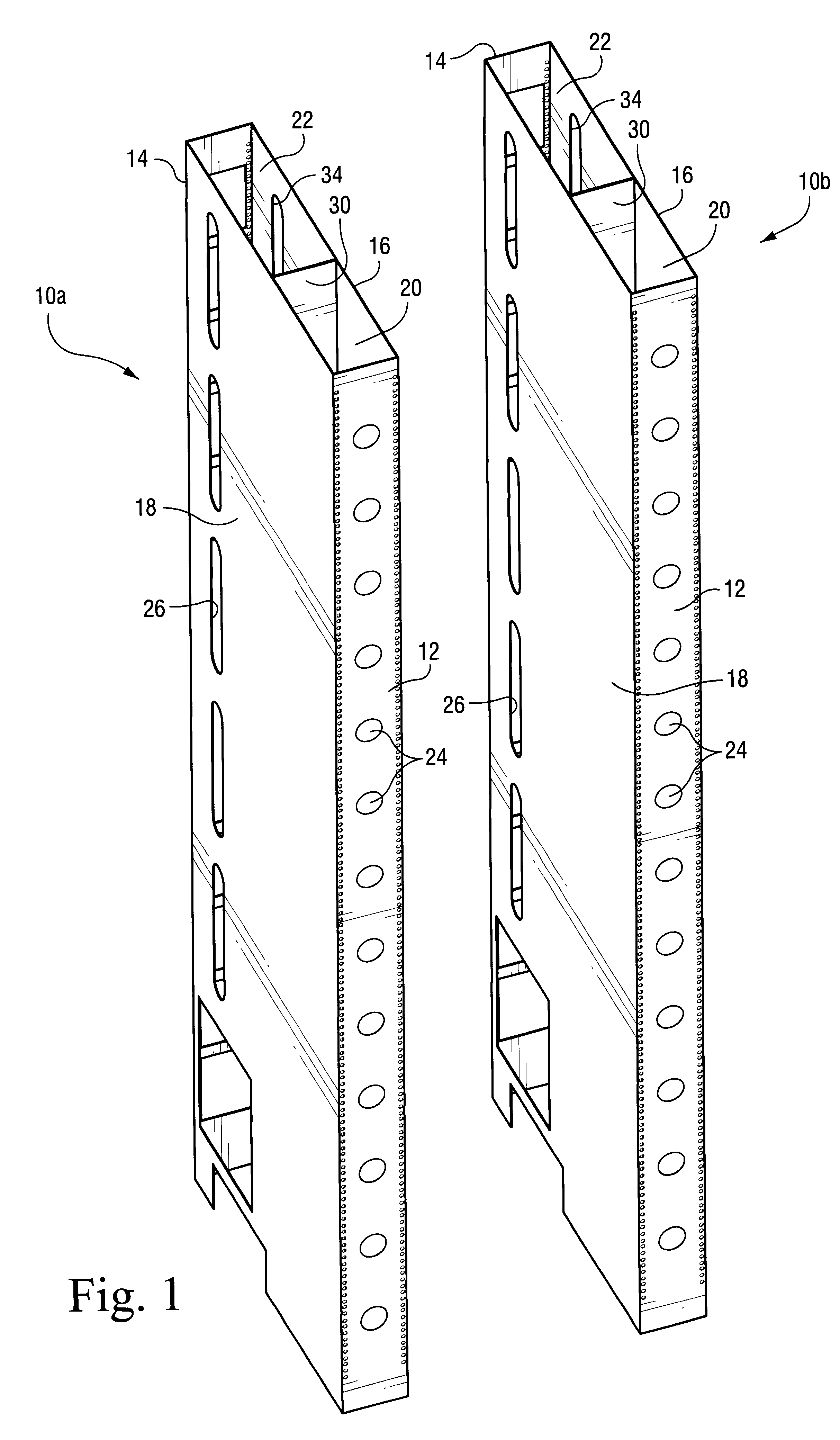
FIG. 1 shows a pair of rack elements 10a and 10b constructed in accordance with a preferred embodiment of the instant invention, and together constituting a complete rack system for mounting equipment thereon. Each of the rack elements (10a and 10b) include a front portion 12 and rear portion 14 and a pair of side portions 16 and 18. The front, rear and pair of side portions are generally configured in the shape of a rectangular box and define an interior of the rack element therebetween. In accordance with the invention, the interior of the rack element is partitioned by, for example, wall 30 into two interior sections 20 and 22.

The front interior section 20 of...


PUM


Abstract

A rack element for mounting electronic equipment thereon, including: a front portion, a rear portion, and a pair of side portions defining an interior of the rack element therebetween. The interior of the rack element is partitioned into a front section and rear section, wherein the front section defines an air duct and the rear section defines a power distribution section. The air duct has an opening at one end thereof for receiving cooling air from an air conditioning system, and the front portion of the rack element includes a plurality of openings therein for enabling the cooling air from the duct to exit therethrough for cooling equipment mounted therein. The power distribution section includes an opening at one end thereof for enabling power cables to enter the power distribution section for powering equipment when mounted on the rack element.

Description

FIELD OF THE INVENTIONThe instant invention relates to electronic equipment racks and, more particularly, to an improved equipment rack for use in data centers and the like that includes integrated cooling ducts and power distribution features. The invention has particular applicability to telecommunications equipment racks and cabinets constructed in accordance with the EIA / TIA standard EIA-310-D ("cabinets, Racks, Panels and Associated Equipment" (ANSI / EIA / 310-D-92)).BACKGROUND AND SUMMARY OF THE INVENTIONEquipment racks and cabinets are used extensively in data communication facilities and the like for the purpose of enabling electronic equipment to be mounted therein. Such racks typically include a rack face which enables the equipment to be mounted such that a bracket on the front of the equipment is secured, using fasteners or the like, to the front face of the rack.Data center processing equipment, such as telecommunications equipment, Web servers and the like, are typically ...

Claims


Application Information

Patent Timeline
Patent Type & Authority Patents(United States)
IPC IPC(8): H04Q1/02H05K7/18H05K7/20
CPCH05K7/186H04Q1/03H04Q1/09H05K7/1491H05K7/20736H04Q1/035H04Q2201/02H04Q2201/06
Inventor BROOME, JOHN P.
Owner SERVER ACQUISITION CORP
Why Eureka
Try Eureka