Transmission method, transmitter and receiver

a technology which is applied in the field of transmission method and receiver, and can solve the problems of inability to operate the system, inability to ignore the influence of call fluctuation for one channel on the entire system, and inability to communicate between the base station and the portable telephon

Inactive Publication Date: 2003-02-11
SONY CORP
View PDF12 Cites 41 Cited by
  • Summary
  • Abstract
  • Description
  • Claims
  • Application Information

AI Technical Summary

Problems solved by technology

Therefore, a time lag occurs before the transmission power is actually increased after receiving the power-up command and as a result, the communication between the base station and the portable telephone may be instantaneously broken.
However, to transmit an information bit stream having a transmission rate of 400K[bit / sec] at a bandwidth of, for example, 4[MHz], the process gain reaches 10 (=4[MHz] / 400[bit / sec]) and thus, the influence of fluctuation of calls for one channel on the entire system cannot be ignored.
Similarly, to transmit an information bit stream having a transmission rate of 800[bit / sec] at a bandwidth of, for example, 4[MHz], it is no longer possible to operate the system without considering the influence of fluctuation of calls for one channel on the entire system.
Thereby, a problem occurs that the interference value suddenly increases to affect other types of communication.
Thereby, a problem occurs that the communication between the base station and a portable telephone is instantaneously broken.
Therefore, when suddenly starting communication at a transmission rate desired by a user from the beginning of the establishment of a communication channel, problems occur that the interference value suddenly increases and the communication between a base station and a portable telephone is instantaneously broken because power control for controlling the increasing interference value cannot follow.

Method used


Image

  • Transmission method, transmitter and receiver
  • Transmission method, transmitter and receiver
  • Transmission method, transmitter and receiver

Examples


first embodiment

(1) First Embodiment

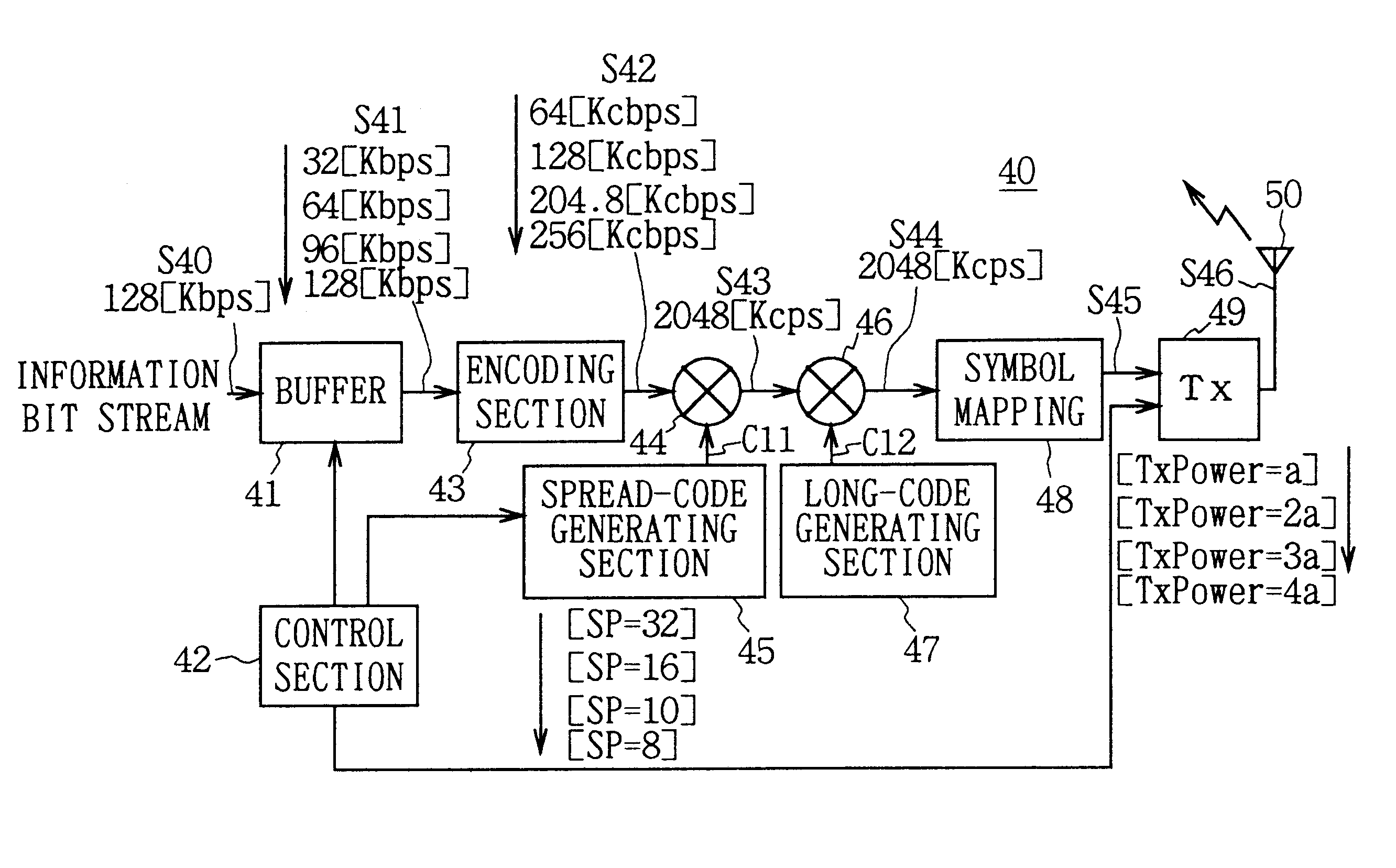
In the case of the present invention, the down communication to be performed from a base station to a portable telephone is described as an example. In FIG. 6, symbol 40 denotes a transmitter of the present invention mounted on a base station as a whole, in which a communication environment using the same frequency band for all adjacent cells, that is, a state in which the number of repetitions of frequency is "1" is set so that an information bit stream S40 is transmitted at a bit rate of 128K[bit / sec] desired by a user by using a bandwidth of 2.048[MHz]. Because the information bit stream S40 transmitted by the user has a high bit rate of 128K[bit / sec], it is possible to communicate not only audio data but also other data at a high speed.

The transmitter 40 first transmits the information bit stream S40 to a buffer 41. The buffer 41 temporarily stores the input information bit stream S40, reads information bit streams S41 while stepwise increasing a bit rate eve...

second embodiment

(2) Second Embodiment

In FIG. 10, symbol 80 denotes a transmitter of the present invention according to a multicarrier communication system as a whole. Also in FIG. 10, it is assumed that a communication environment is using the same frequency band for all adjacent cells, that is, a state in which the number of repetitions of frequency is "1" is set and the entire bandwidth of 3.2[MHz] is used, and the communication of 32K[bit / sec] can be executed at a bandwidth of 100[KHz] constituted with 24 subcarriers. In this case, because an information bit stream S80 to be transmitted by a user has a high bit rate of 128K[bit / sec], it is possible to communicate not only audio data but also other data at a high speed.

The transmitter 80 first transmits the information bit stream S80 to a buffer 81. The buffer 81 temporarily stores the input information bit stream S80, reads information bit streams S81 while stepwise increasing a bit rate every predetermined time interval and every predetermined ...

third embodiment

(3) Third Embodiment

In FIG. 14, symbol 100 denotes a multicarrier-communication transmitter of the present invention as a whole. Also in FIG. 14, a communication environment using the same frequency band for all adjacent cells, that is, a so-called state in which the number of repetitions of frequency is "1" is set and not only audio data but also data can be communicated at a high speed by transmitting an information bit stream S100 of 128K[bit / sec] through a, channel having a bandwidth of 400[KHz] constituted with 96 subcarriers.

The transmitter 100 first transmits the information bit stream S100 to a buffer 101. The buffer 101 temporarily stores the input information bit stream S100, reads an information bit stream S101 while stepwise increasing a bit rate every predetermined time interval and predetermined number of bits in accordance with a control signal supplied from a control section 102 and transmits the stream S101 to an encoding section 103.

In this case, the control sectio...


PUM


Abstract

A transmission method and apparatus which perform communication without interfering with other types of communication is provided. A transmission symbol stream is generated by applying predetermined modulation processing to an encoded bit series obtained by encoding an information bit series of a predetermined transmission rate. A transmission signal generated by applying the transmission processing to the transmission symbol series is then transmitted. A transmission-information bit series with a transmission rate lower than the predetermined transmission rate is generated first. Transmission of the transmission signal generated in accordance with the transmission-information bit series then begins through a predetermine communication channel. The low transmission rate is then sequentially stepwise increased to the predetermined transmission rate. Transmission is performed while sequentially stepwise increasing the number of communication channels in accordance with the sequential stepwise increase of the low transmission rate.

Description

1. Field of the InventionThe present invention relates to a transmission method, a transmitter and a receiver, which is preferably applied to a cellular radio-communication system such as a portable telephone system.2. Description of the Related ArtA conventional cellular radio-communication system is constituted so that an area for which communication services are provided is divided into cells of a desired size, a base station serving as a fixed radio station is set in each of the cells, and a portable telephone serving as a mobile radio station performs radio communication with a base station in a cell in which the portable telephone is present.In the above case, various communication systems are considered between a portable telephone and a base station. Typical systems are the code division multiple access (CDMA) system and the time division multiple access (TDMA) system.The CDMA system is a communication system for transmitting a narrow-band modulated wave (primary modulation)...

Claims


Application Information

Patent Timeline
Patent Type & Authority Patents(United States)
IPC IPC(8): H04L5/02H04B1/707H04B7/26H04B7/005H04J13/00H04L27/26H04W4/00H04W28/00H04W52/26H04W88/02
CPCH04B1/707H04B7/264H04W52/267H04L27/2608H04L5/026H04L5/0044
Inventor SAKODA, KAZUYUKISUZUKI, MITSUHIRO
Owner SONY CORP
Why Eureka
Try Eureka