Hand-held suction pump

a suction pump and hand-held technology, applied in the field of hand-held suction pumps, can solve problems such as subject to further improvemen

Inactive Publication Date: 2003-02-18
ARACARIA
View PDF11 Cites 109 Cited by
  • Summary
  • Abstract
  • Description
  • Claims
  • Application Information

AI Technical Summary

Problems solved by technology

The known hand-held suction device has been proven to satisfy the aforementioned need but may be subject to further improvement regarding some noise generated by the intermittent air flow which must necessarily exit the device during operation.

Method used


Image

  • Hand-held suction pump
  • Hand-held suction pump
  • Hand-held suction pump

Examples


Embodiment Construction

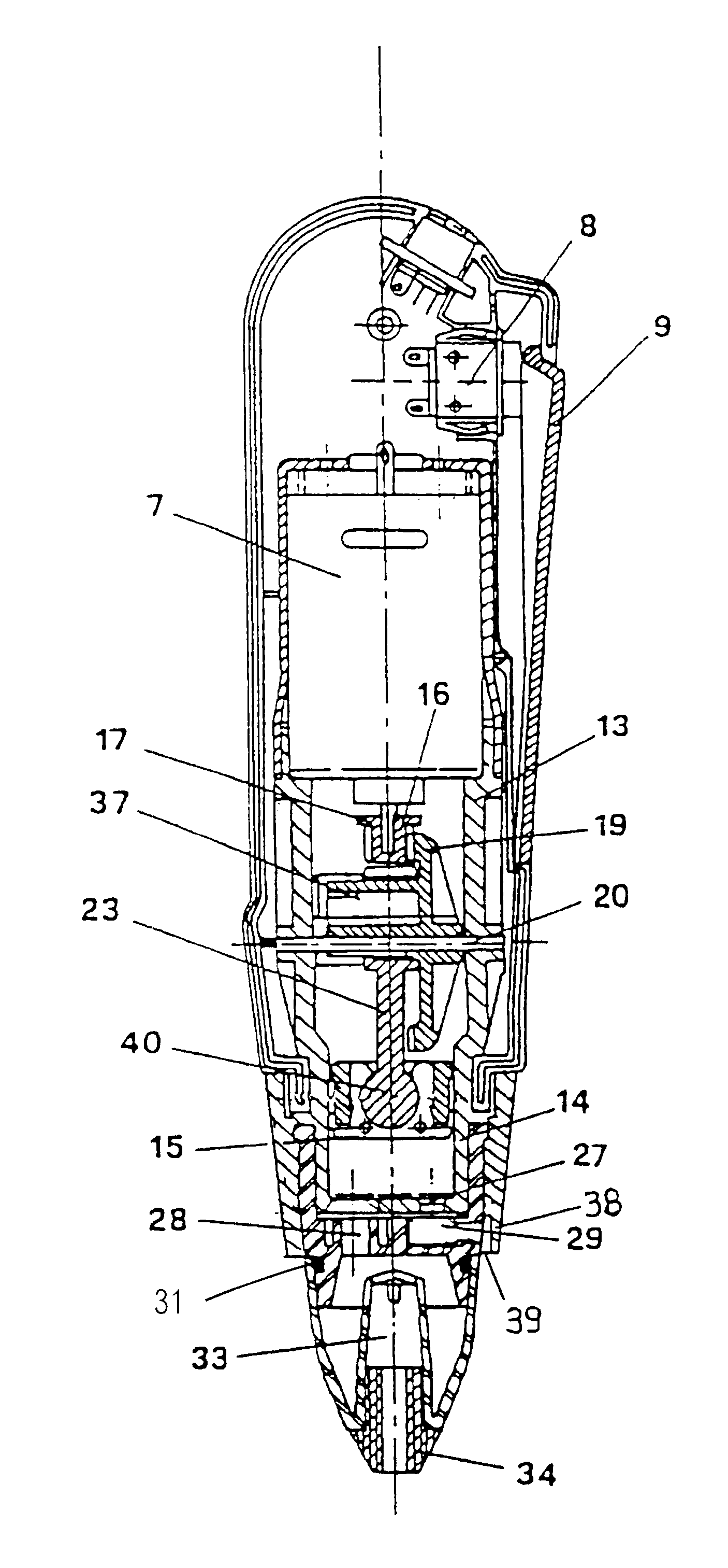
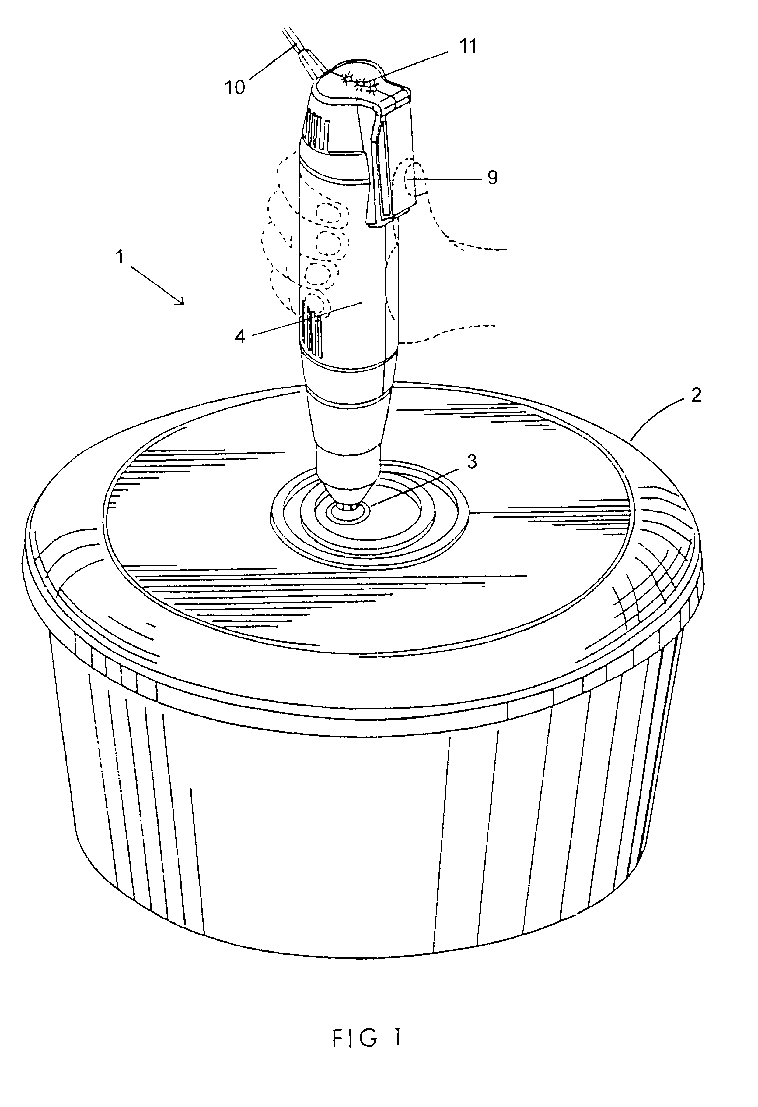
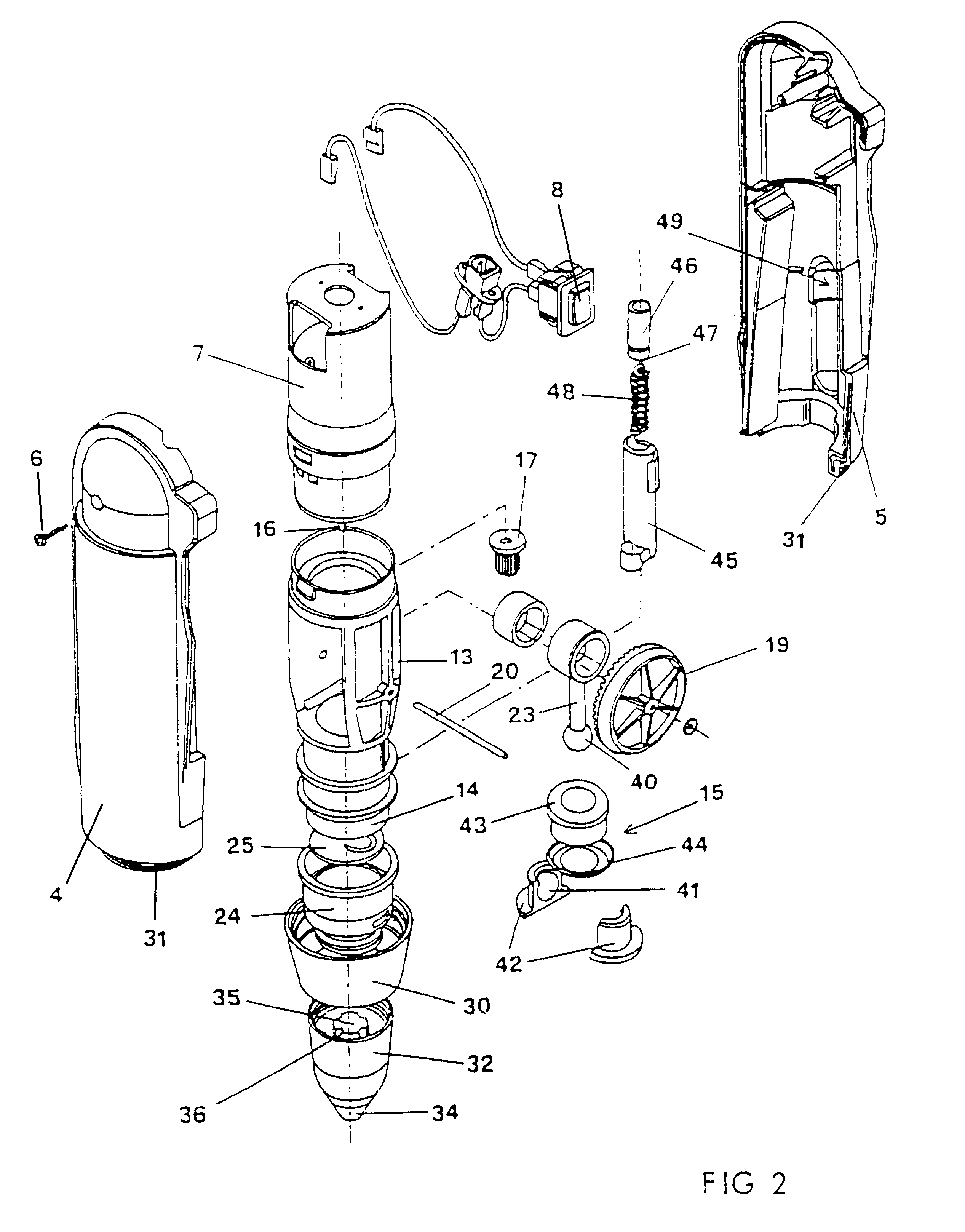
With reference to FIGS. 1 to 3, the suction pump according to the invention has been indicated as a whole with reference number 1. FIG. 1 shows this suction pump 1 being applied to suction valve 3 of a container 2, in which a vacuum is to be established.

As is more easily visible in the exploded view of FIG. 2, the hand-held suction pump 1 comprises an elongated outer casing partly formed by two substantially identical halves 4 and 5, assembled with screws 6. In the upper part of the outer casing, an electric motor 7 is disposed to be operated by a press switch 8 actuated by a pivoted key 9. In these figures part of a power cable 10 is shown which is present for case that the motor 7 is driven by line current. It is evident, however, that the suction pump could also be driven by a battery, which is possibly rechargeable by line current. The figures also depict three LEDs 11 of different colours, the status of which is determined by the load of the motor 7 and which serve to signal th...


PUM

PropertyMeasurementUnit
angleaaaaaaaaaa
deflecting angleaaaaaaaaaa

Abstract

A hand-held suction pump for creating a vacuum in a container (2) provided with a suction valve (3), comprising an elongated outer casing in which an electric motor (7) and a piston pump (14, 15) driven by the motor (7) are accommodated, wherein the pump chamber (14) of the piston pump is connected by an inlet valve and a suction duct (28) to a hollow tip (34) at the free end of the casing for direct coupling with the suction valve of the container, the pump chamber being further connected by an outlet valve to an exhaust duct (29) having a duct opening on the outer surface of the wall of the outer casing for porting an exhaust flow to the exterior of the outer casing. In order to reduce noise caused by the exhaust flow, the duct opening of the exhaust duct (29) is overlapped by a baffle (38) which is separated by a gapped distance from the outer surface of the wall of the outer casing so as to deflect the exhaust flow exiting the duct opening by a substantial angle.

Description

FIELD OF THE INVENTIONSThe inventions described below relate the field of hand-held suction pumps intended for use in evacuating containers.BACKGROUND OF THE INVENTIONSThe invention refers to a hand-held suction pump for creating a vacuum in a container provided with a suction valve, comprising an elongated outer casing in which an electric motor and a piston pump driven by the motor are accommodated, wherein the pump chamber of the piston pump is connected by an inlet valve and a suction duct to a hollow tip at the free end of the casing for direct coupling with the suction valve of the container, the pump chamber being further connected by an outlet valve to an exhaust duct having a duct opening on the outer surface of the wall of the outer casing for porting an exhaust flow to the exterior of the outer casing.A hand-held suction pump of the aforementioned kind is disclosed in EP 0 510 360 A. It is useful especially in the household field for creating a high vacuum in household co...

Claims


Application Information

Patent Timeline
Patent Type & Authority Patents(United States)
IPC IPC(8): B65B31/04
CPCB65B31/047
Inventor LANZA, FABRIZIO
Owner ARACARIA
Why Eureka
Try Eureka