Rotary drum seeder

a rotary drum and seeder technology, applied in the field of rotating drum seeders, can solve the problems of substantial amount of feedstock waste, detriment to the prior art system, and unappealing aesthetically, and achieve the effects of convenient use, convenient interchangeability, and enhanced system portability

Inactive Publication Date: 2003-02-18
FEDCO SYST
View PDF9 Cites 18 Cited by
  • Summary
  • Abstract
  • Description
  • Claims
  • Application Information

AI Technical Summary

Benefits of technology

Optionally, the seed dislodging device disposed within the rotary drum is a pressure shoe. The pressure shoe, which provides a continuous supply of pressurized fluid, dislodges the seeds when the dimpled seed cavities disposed on the outer surface of the drum pass over the shoe, thereby permitting an intermittent burst of pressurized fluid to pass through a tubular bore that connects the cavity to the substantially hollow internal portion of the rotary drum assembly's rotatable drum, thus overcoming seed adhesion caused by the internal vacuum action. The rotary drum seeder optionally includes an air knife disposed between the hopper discharge and the rotary drum. The air knife uses a sheet-like air scraper to shake loose extra seeds adhering to the drum surface caused by residual vacuum around the apertures. This ensures that a consistent, repeatable quantity of seeds is deposited on the target food substrates. To ensure that an adequate supply of seeds is reaching the hopper discharge through the gate, an optional hopper agitator or vibrator may be added. This is valuable in situations where the seeds, which by virtue of their shape or hygroscopic nature, could stick together and would otherwise inhibit their normal free-flow from the seed hopper to the hopper discharge. The primary support structure of the rotary drum seeder may also include mounted wheels to enhance system portability. Similarly, a rotary drum height adjuster can be included to adjust

Problems solved by technology

An unfortunate concomitant to this requirement is that the quantity of seeds placed on the surface of each bun can be highly non-uniform, resulting in an aesthetically unappealing, and possibly unappetizing final product.
Furthermore, seed spillage and re

Method used


Image

  • Rotary drum seeder
  • Rotary drum seeder
  • Rotary drum seeder

Examples


Embodiment Construction

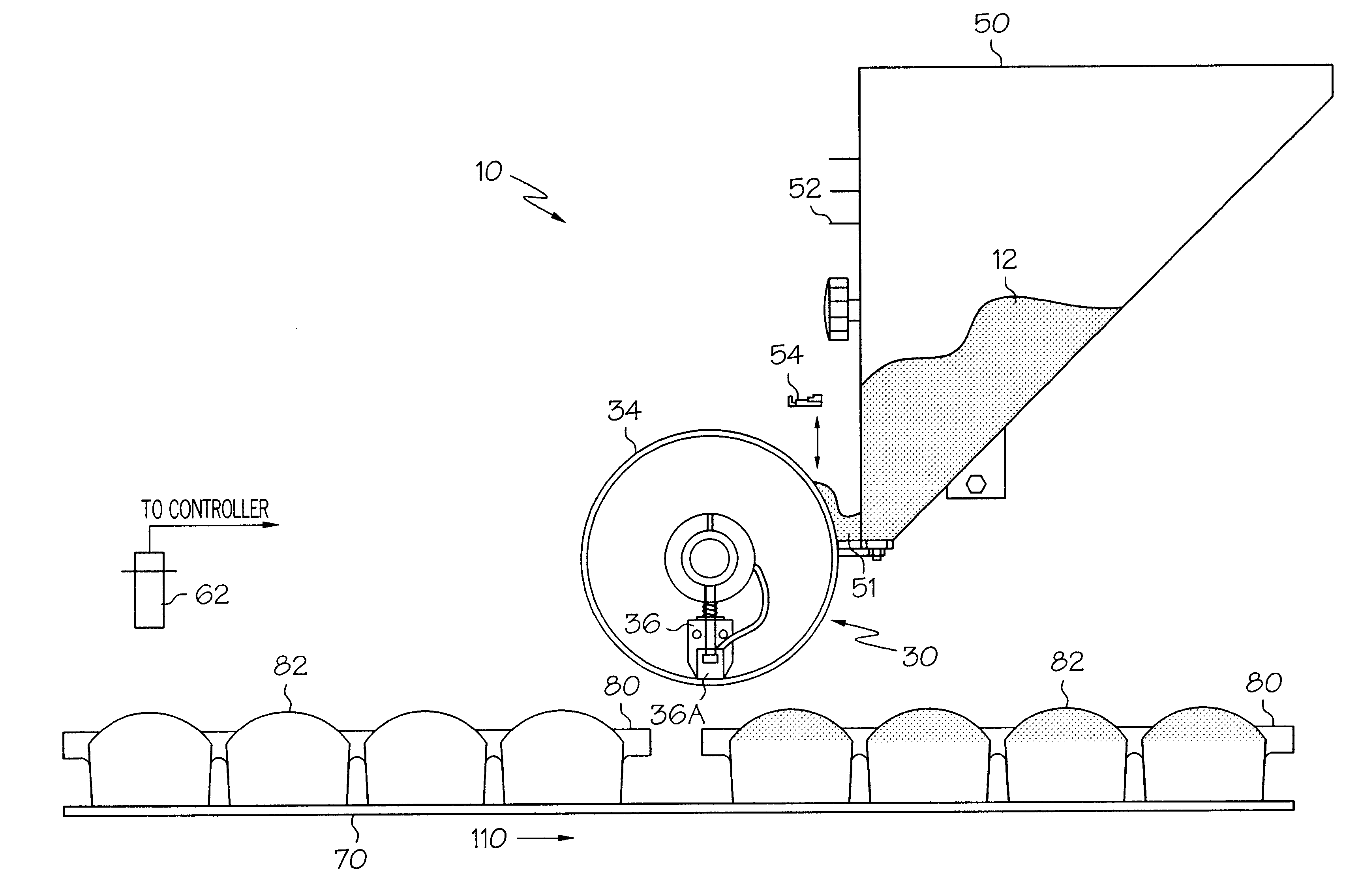
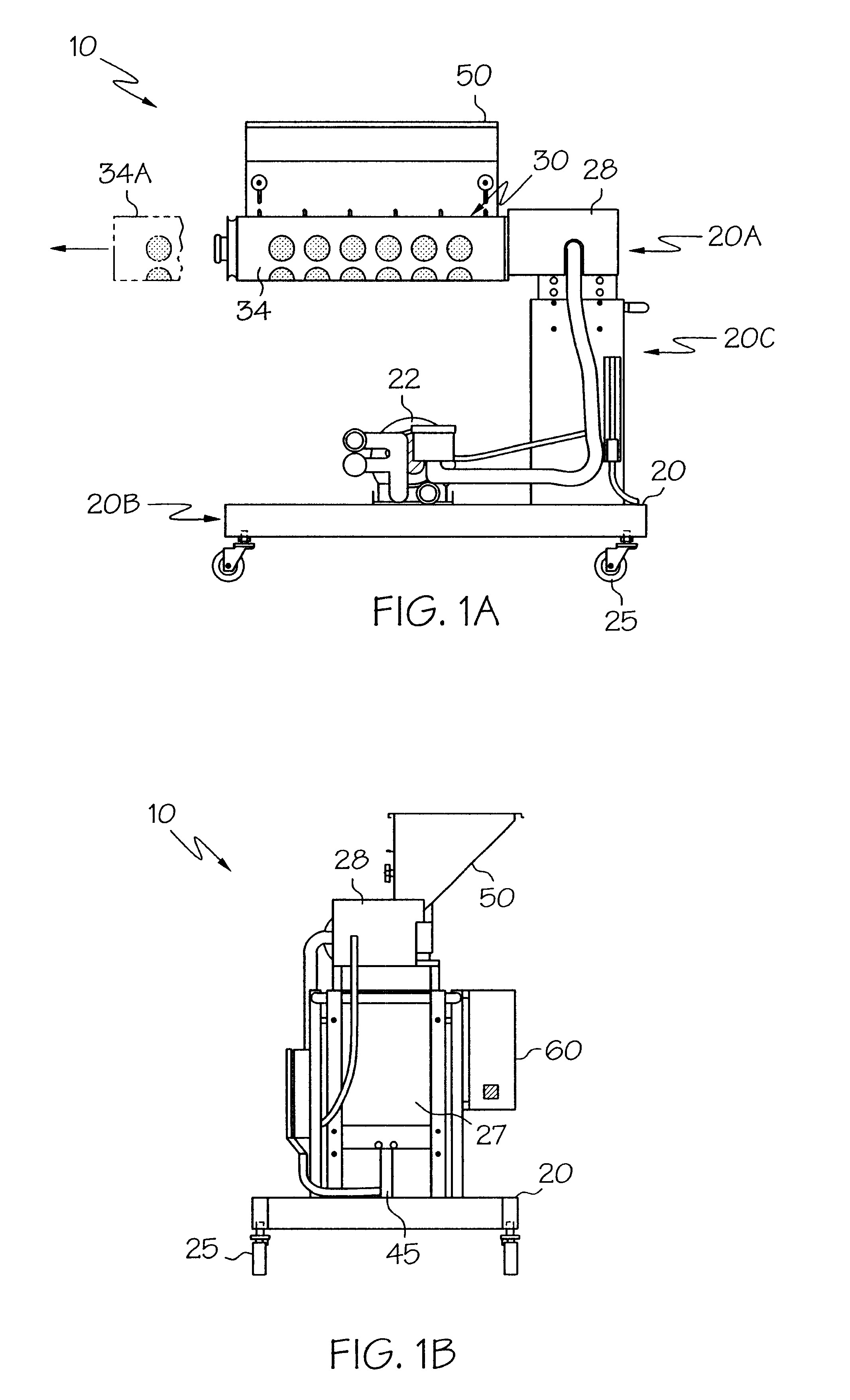
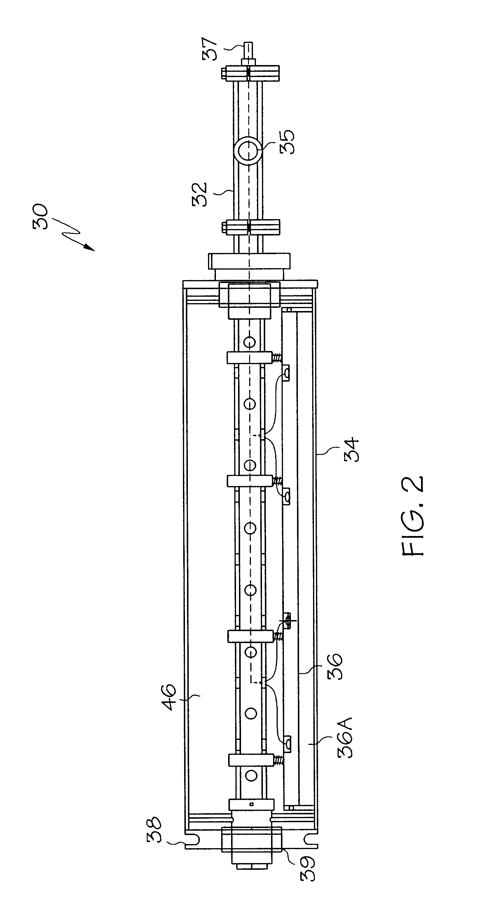
Referring initially to FIGS. 1A and 1B, a rotary drum seeder system 10 according to the present invention comprises a primary support structure 20, in the form of a cantilevered chassis or frame to support the system components. Typically, primary support structure 20 is made of a food-grade structural material, such as stainless steel. The primary support structure 20 comprises three main portions: an upper arm 20A, a lower arm 20B and an upstanding interconnect 20C. To improve the portability of system 10, lower arm 20B of primary support structure 20 is mounted to level swivel wheels, or casters 25. The system 10 also includes a pump 22, a main drive 27 with clutch 28 to provide rotational power to a rotary drum assembly 30, a hydraulic drum height adjuster 45, a seed hopper 50, and a control panel 60. Partial cutaway 34A of a rotatable drum 34 (discussed in more detail below) in rotary drum assembly 30 is used to show the direction of drum 34 removal. Quick-release couplings (no...


PUM


Abstract

A rotary drum seeder for depositing seeds onto food products. The seeder includes a primary support structure, rotary drum assembly, seed hopper, feed gate disposed between the seed hopper and a hopper discharge, and controller. The surface of a rotatable drum of the drum assembly includes repeating patterns made up of apertures. Seeds are selectively adhered to and dislodged from the apertures by high and low pressure fluids provided to the apertures. The low and high pressure fluids come from a vacuum source and a high pressure source, respectively. The vacuum source causes seeds to adhere to the apertures, while the high pressure source generates a localized positive fluid pressure in a seed dislodging device disposed within the rotary drum, thereby forcing the seeds from the apertures when they pass over the seed dislodging device. A boundary layer air knife is used to remove excess seeds from the surface of the rotary drum. Signals from the controller direct the drum to rotate a specified amount in response to the arrival of a conveyor-carried tray of product onto which seeds are to be deposited.

Description

BACKGROUND OF THE INVENTIONThe present invention relates to a system for dispensing particulate matter onto a substrate, and more particularly to a rotating drum seeder for placing sesame seeds onto a plurality of buns traveling at a high rate of speed along a conveyor.The use of seed-depositing devices is well known in the art. In various food processing applications, these devices are used to introduce seeds and related edible flavorings to bakery products, such as rolls, loaves of bread and sandwich buns. In the production of seeded sandwich buns, a continuous conveyor, often carrying trays containing a number of buns, is passed under a seed-dispensing device including a spreader connected to a seed hopper. Typically, the spreader includes an inlet section which receives a continuous flow of seed from the seed hopper, and a toothed auger to agitate and dispense the seeds onto buns passing beneath on a conveyor. In order to manufacture large quantities of finished product in a tim...

Claims


Application Information

Patent Timeline
IPC IPC(8): A23P1/08A23G3/02A23G3/20A21C15/00A21C9/04A21C9/00
CPCA21C9/04A23P1/082A23G3/2076A21C15/002A23P20/12
Inventor LANG, KIRK ALAN
Owner FEDCO SYST
Why Eureka
Try Eureka