Leveling mount

a leveling mount and mount technology, applied in the direction of machine frames, stand/trestles, kitchen equipment, etc., can solve the problems of bolt failure, difficulty in supporting machinery, and problems in their application and us

Inactive Publication Date: 2003-02-18
S & W MFG
View PDF14 Cites 48 Cited by
  • Summary
  • Abstract
  • Description
  • Claims
  • Application Information

AI Technical Summary

Benefits of technology

A further object of the invention is to provide an easy, simple, and efficient means of replacing the elastomeric non-skid base pad by providing a snap-on male circumferential locking elastomeric pad which locks in place over female circumferential indentations on the base mount with easy removability and replacement after wear or damage.
A still further object is to permit engineering of the elastomeric base pad to required needs of the installation, to modify the thickness, size, and material of the base pad as needed to provide a larger base pad to reduce vibration effects upon the mounted equipment or support surface or to overcome environmental conditions.
An additional object is to provide an equipment mount assembly with design flexibility comprising a tapped ball socket suitable for receiving a tapped ball or a fixed stud on equipment, wherein the leveling mount needs to be easily removed, a larger than standard stud can be attached to or mounted in the leveling mount base or the mounted equipment already has a fixed stud which needs to be inserted in the leveling mount base.
This invention relates to a leveling mount for installation of equipment in locations wherein the supporting surface may not be a level planar surface. The invention comprises a ball and socket arrangement and self-leveling mount which adjusts to uneven surfaces without operative adjustments and a non-skid elastomeric base pad to restrict the movement of the equipment from its designated position during operation despite vibratory or oscillatory movement of the equipment. The non-skid elastomeric base pad utilizes male-female design elements to allow easy replacement upon damage, wear, or installation requirements. The non-skid elastomeric base pad permits the equipment to be temporarily repositioned or moved to uneven surfaces without damage to the support surface. The mount alternatively comprises a tapped ball socket suitable for receiving a separately sized ball end stud, or a threaded equipment stud, said separately sized ball end stud or threaded equipment stud being integral supports of supported equipment.

Problems solved by technology

The use of a bolt as a load bearing leg for the support of machinery can pose difficulties if the machine is to be placed upon a surface that tilts or requires the machine be in a fixed position perpendicular to the supporting surface.
The tilt of the supporting bolt can cause a resulting stress upon the bolt, which results in the failure of the bolt.
However, objectionable aspects of devices ordinarily available as equipment leveling devices can restrict the utility of such devices and may create problems in their application and use.
A disadvantage of the mounting device taught by Freeman '075 is that the ball and socket arrangement is not self-leveling.
While the arrangement permits the load to be evenly distributed about the spherical surface of the socket, the ball is not free to move from the vertical to adjust for unevenness of the supporting surface during installation of the machine-leveling device.
As Freemen '075 teaches, shims can be difficult to use if the machine is to be placed on a surface that varies in elevation between different mount locations.
The machine mount apparatus of the May '852 patent and the supported machine are not free to be easily moved after engagement with the supporting floor.

Method used


Image

  • Leveling mount
  • Leveling mount

Examples


Embodiment Construction

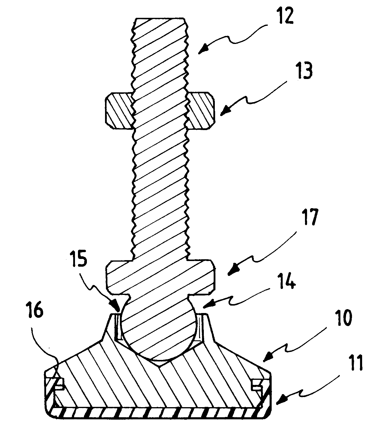
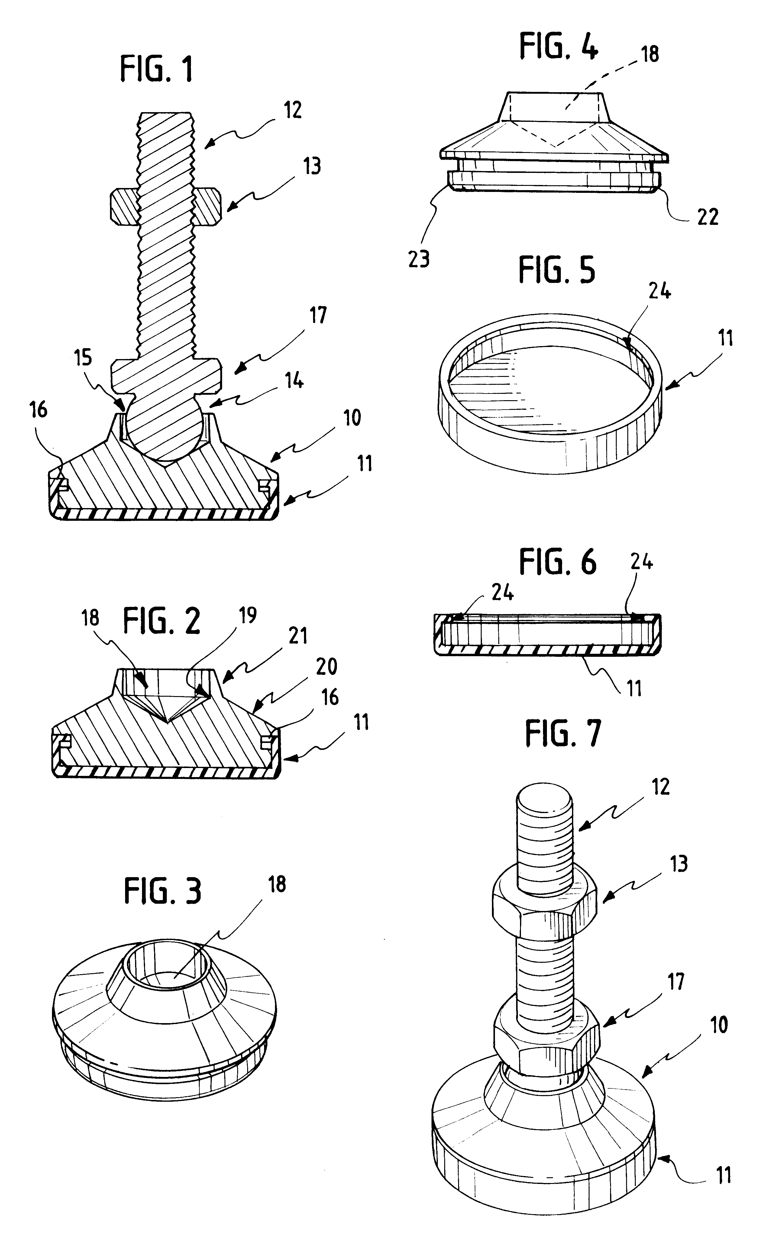
The present invention relates to a unique leveling mount to be installed on equipment to support and level equipment on an uneven or non-level surface utilizing a ball and socket arrangement. The leveling mount is used to support and level a wide variety of equipment including machine tools, electronic equipment, packaging and printing machines. The mount is constructed of carbon or alloy steel with a plated finish with a non-skid cup pad of elastomeric material. The leveling mount engages the mounting stud so that the mounting stud can freely swivel 71 / 2.degree. from the vertical to all sides of the centerline through a circular 360.degree. movement in a ball socket. The mounting stud is a threaded metal bar of carbon steel or alloy steel with a ball end which swivels in the leveling mount. Alternatively, a fixed stud already attached to the supported equipment can be engaged with the threaded ball socket of the leveling mount. The ball and socket arrangement allows for a self-leve...


PUM


Abstract

A leveling mount is disclosed for equipment in temporary or permanent installations wherein the supporting surface can be a non-level planar surface. A ball and socket support stud provides a self-leveling adjustment of support. An elastomeric removable mount base pad provides non-skid means. Limited swivel and radial movement of the ball and socket support stud are maintained. The leveling mount base can engage a support stud affixed to the supported equipment.

Description

The field of this invention relates to equipment leveling devices. The present invention is a device to permit installation of equipment in temporary or permanent locations wherein the supporting surface may not be a level planar surface. Leveling elements are accordingly required to supply adjustable support for the equipment to overcome the uneven support surface in order for the equipment to be leveled despite the non-planar support surface. The present invention is also adapted to permit the equipment to be repositioned or moved to uneven surfaces without loss of stability upon an uneven or non-level surface in non-skid applications.The term "non-skid" refers to the substantial anchoring of equipment in a specific location upon what can be described as a non-planar surface so that the equipment does not move from its designated position during operation despite vibratory or oscillatory movement of the equipment. The present invention accordingly is a unique leveling mount to be ...

Claims


Application Information

Patent Timeline
Patent Type & Authority Patents(United States)
IPC IPC(8): A47B91/00A47B91/06F16M7/00
CPCF16M7/00A47B91/066
Inventor BURR, WILLIAM J.
Owner S & W MFG
Why Eureka
Try Eureka