Electrochemical cell

Inactive Publication Date: 2003-02-18
LIFESCAN INC
View PDF85 Cites 366 Cited by
  • Summary
  • Abstract
  • Description
  • Claims
  • Application Information

AI Technical Summary

Problems solved by technology

Generally this method requires sufficient separation of the electrodes so that electrolysis products at one electrode cannot reach the other electro

Method used


Image

  • Electrochemical cell
  • Electrochemical cell
  • Electrochemical cell

Examples


Embodiment Construction

The invention will now be particularly described by way of example only with reference to the accompanying schematic drawings wherein:

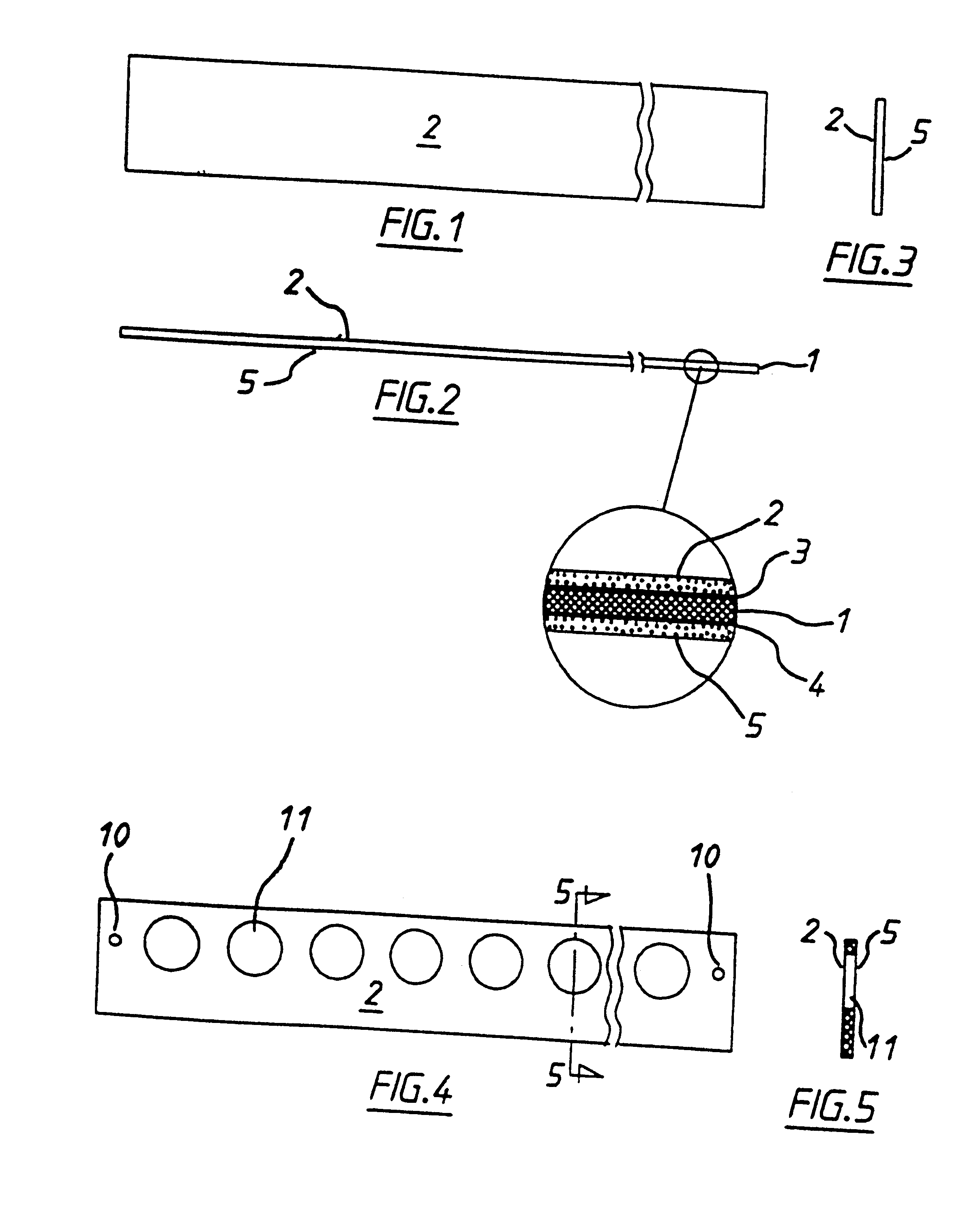
FIG. 1 shows the product of manufacturing step 2 in plan.

FIG. 2 shows the product of FIG. 1 in side elevation.

FIG. 3 shows the product of FIG. 1 in end elevation.

FIG. 4 shows the product of manufacturing step 3 in plan.

FIG. 5 shows the product of FIG. 4 in cross-section on line 5--5 of FIG. 4.

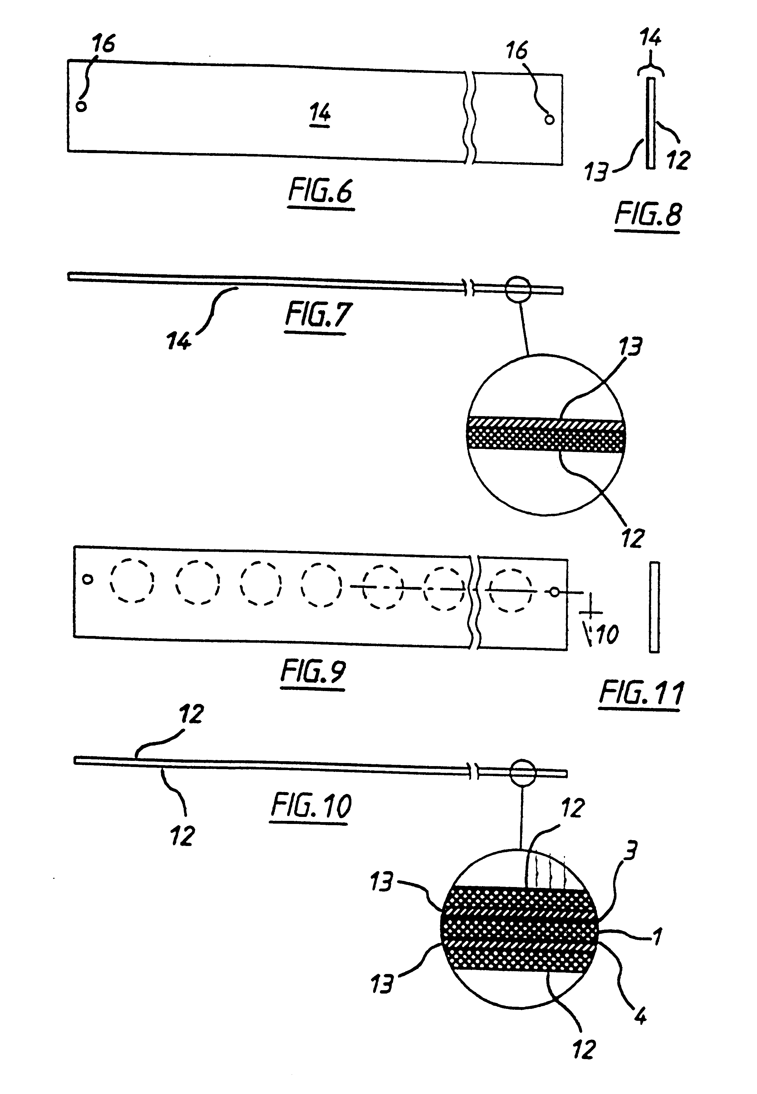
FIG. 6 shows the product of manufacturing step 5 in plan.

FIG. 7 shows the product of FIG. 6 in side elevation.

FIG. 8 shows the product of FIG. 6 in end elevation.

FIG. 9 shows the product of manufacturing step 7 in plan.

FIG. 10 is a cross-section of FIG. 9 on line 10--10.

FIG. 11 shows the product of FIG. 9 in end elevation.

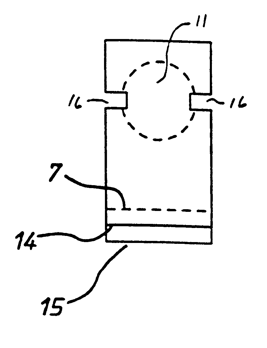
FIG. 12 shows a cell according to the invention in plan.

FIG. 13 shows the call of FIG. 12 in side elevation.

FIG. 14 shows the cell of FIG. 12 in end elevation.

FIG. 15 shows a scrap portion of a second embodiment of the invention in enlarged sect...


PUM

PropertyMeasurementUnit
Thicknessaaaaaaaaaa
Shapeaaaaaaaaaa
Distanceaaaaaaaaaa

Abstract

A method of manufacture of a thin layer electrochemical cell (FIGS. 12, 14) comprising the steps of:forming an aperture (11) extending through a sheet (1) of electrically resistive material, said aperture defining a side wall of the cell,mounting a first thin electrode layer (13) to one side of the sheet and extending over aperture (11) whereby to define a cell first end wall,mounting a second thin electrode layer (13) to the other side of the sheet and extending over aperture (11) whereby to define a second cell end wall in substantial overlying registration with the first electrode, andproviding means (16) for admission of a liquid into the cell.

Description

BACKGROUND ARTThe invention herein described is an improvement in or modification of the invention described in our co-pending U.S. application Ser. No. 08 / 981,385, entitled ELECTROCHEMICAL CELL, filed on Dec. 18, 1997, the contents of which are incorporated herein by reference.The invention will herein be described with particular reference to a biosensor adapted to measure the concentration of glucose in blood, but it will be understood not to be limited to that particular use and is applicable to other analytic determinations.It is known to measure the concentration of a component to be analysed in an aqueous liquid sample by placing the sample into a reaction zone in an electrochemical cell comprising two electrodes having an impedance which renders them suitable for amperometric measurement. The component to be analysed is allowed to react directly or indirectly with a redox reagent whereby to form an oxidisable (or reducible) substance in an amount corresponding to the concent...

Claims


Application Information

Patent Timeline
IPC IPC(8): C12Q1/00G01N27/403G01N27/49G01N27/30G01N33/487
CPCC12Q1/004G01N27/3272C12Q1/006
Inventor HODGES, ALASTAIR MCINDOEBECK, THOMAS WILLIAMJOHANSEN, ODDVARMAXWELL, IAN ANDREW
Owner LIFESCAN INC
Why Eureka
Try Eureka