Ballast control IC with minimal internal and external components

a ballast control and internal and external component technology, applied in the field of electronic ballast, can solve the problems of lack of desirable features, and the need for additional components inside and outside the chip,

Inactive Publication Date: 2003-02-25
INFINEON TECH AMERICAS CORP
View PDF4 Cites 40 Cited by
  • Summary
  • Abstract
  • Description
  • Claims
  • Application Information

AI Technical Summary

Benefits of technology

The present invention overcomes the deficiencies of the prior art, such as those described above, by providing an electronic ballast that utilizes fewer comparators and combines the functionality of sub-circuits, thereby reducing the number of internal and external components required.

Problems solved by technology

Although the IR2155 offers a vast improvement over prior ballast control circuits, it lacks a number of desirable features such as the following: (i) a start-up procedure which ensures a flash-free start without an initial high voltage pulse across the lamp, (ii) non-zero voltage switching protection circuitry, (iii) over-temperature shutdown circuitry, (iv) DC bus and AC on / off control circuitry, and (v) near or below resonance detection circuitry.
These and other configuration details result in additional components being required both inside and outside the chip.

Method used


Image

  • Ballast control IC with minimal internal and external components
  • Ballast control IC with minimal internal and external components
  • Ballast control IC with minimal internal and external components

Examples


Embodiment Construction

Overview:

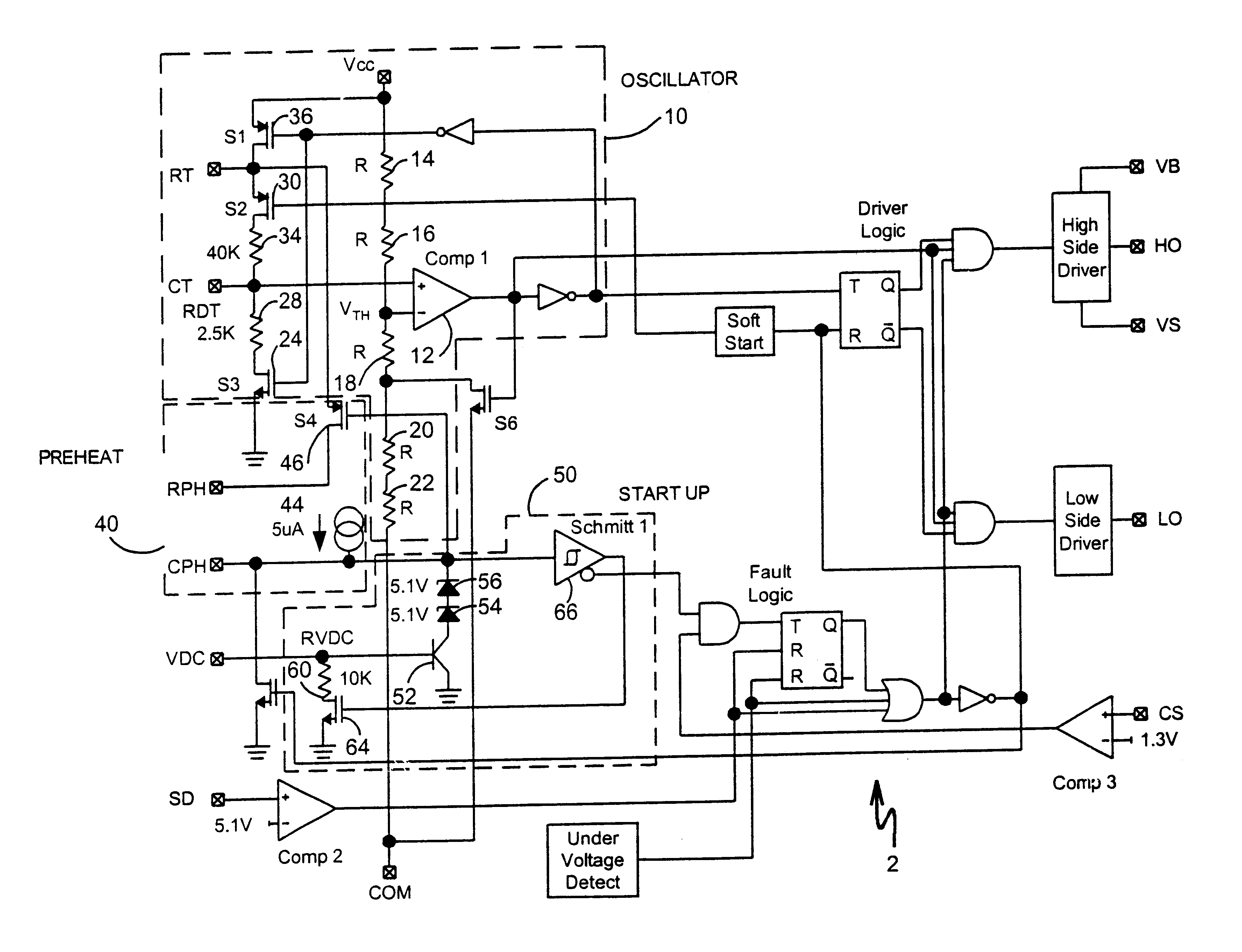
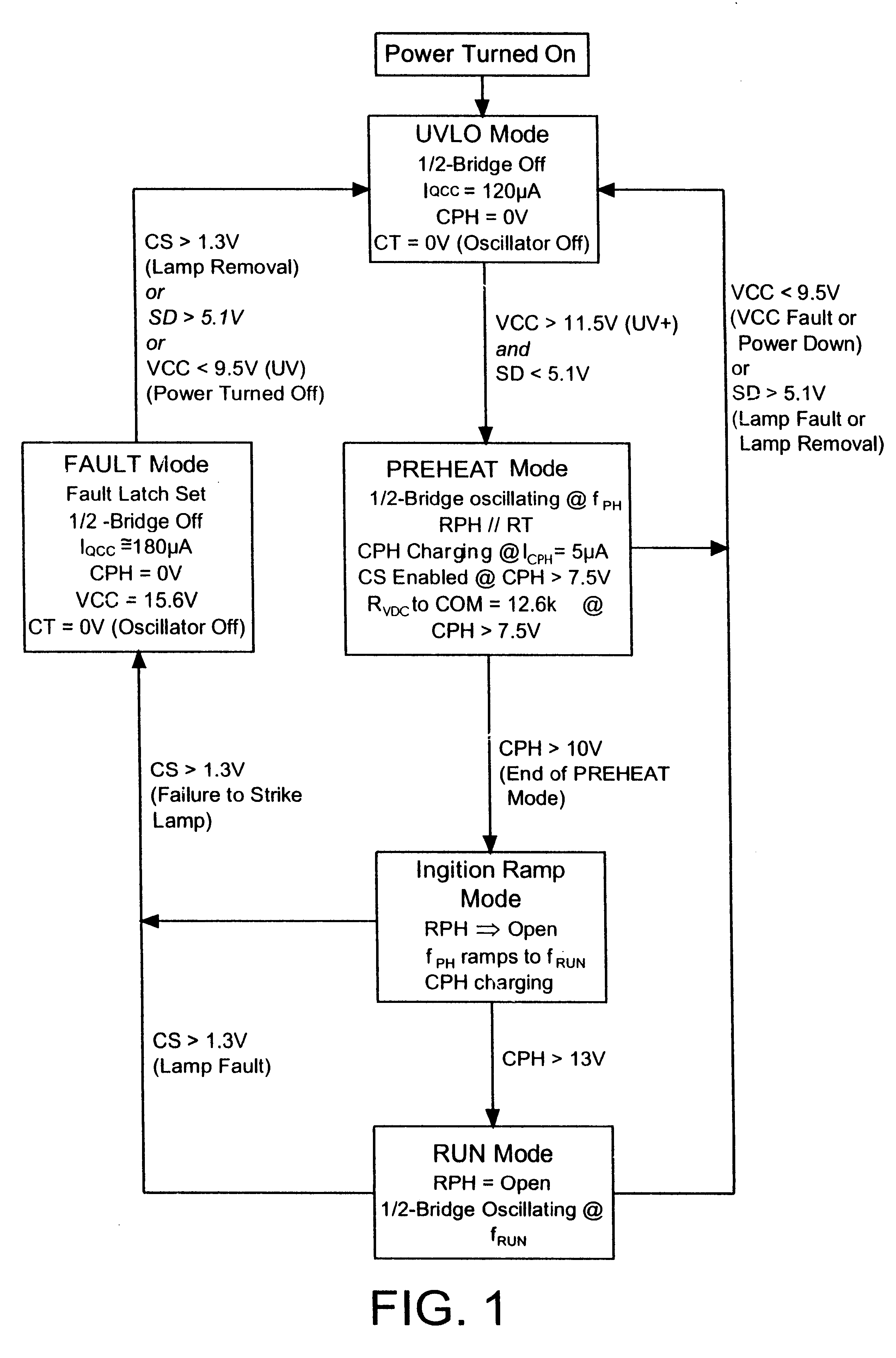
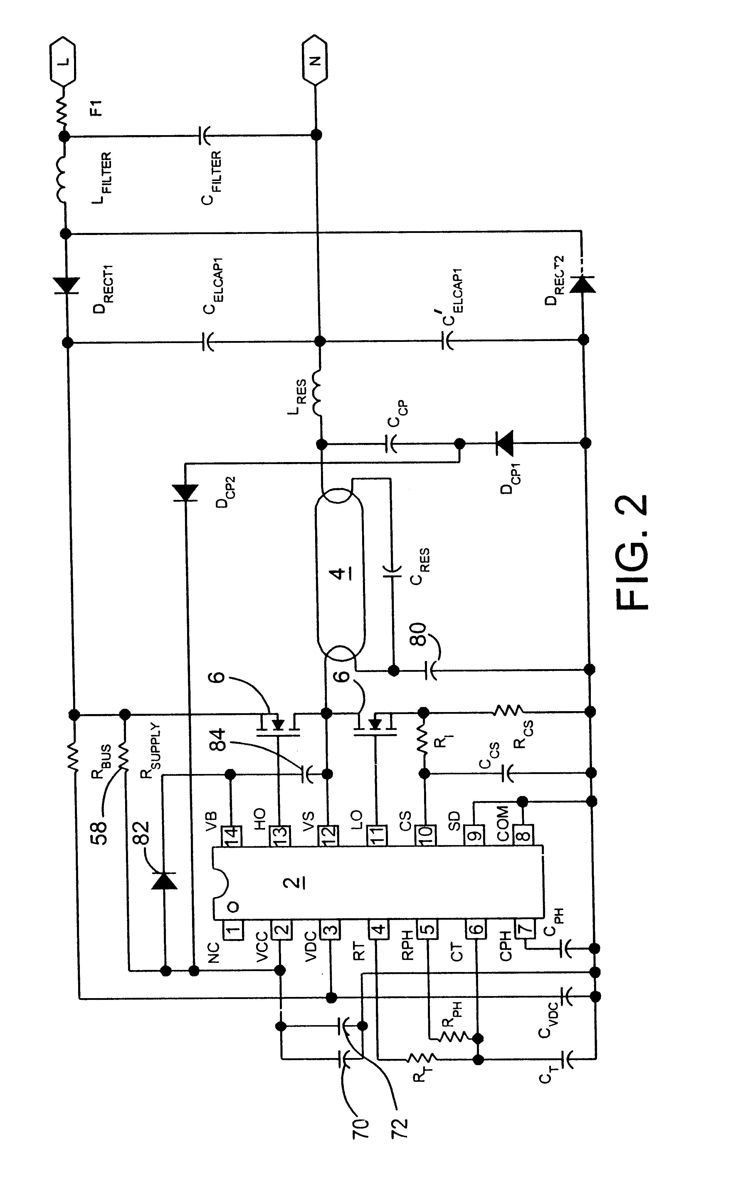
Referring first to FIG. 1, a state diagram is shown that is incorporated into the operation of the integrated circuit (IC) 2 of the present invention for controlling an electronic (rapid start) fluorescent lamp ballast. FIG. 2 illustrates a typical connection diagram for driving a single fluorescent lamp 4 with the integrated circuit 2 of the present invention. FIG. 3 illustrates a basic block diagram of the integrated circuit 2 of the present invention. Many of the aspects of the present invention shown in FIGS. 1-3 are similar to the disclosure of U.S. Pat. No. 6,211,623 to Wilhelm et al. issued Apr. 3, 2001 and incorporated herein by reference, and will be discussed further below. However, significant aspects and advantages of the present invention, particularly with respect to oscillator 10, preheat circuit 40 and start-up circuit 50 shown in FIG. 3, will be discussed, as follows:

Oscillator:

FIG. 4 is a detailed schematic of oscillator circuit 10 according to the present...


PUM


Abstract

A ballast controller integrated circuit which executes a specific set of instructions via an integrated state diagram architecture to control a fluorescent lamp or high intensity discharge lamp and protect the ballast. The state diagram architecture controls powering up and down of the IC and the half-bridge circuit driven by the IC, preheating and striking of the lamp, running of the lamp, sensing for numerous possible fault conditions, and recovering from these fault conditions based on the normal maintenance of a lamp, while requiring fewer internal and external components than previous electronic ballasts.

Description

1. Field of the InventionThe present invention relates to an electronic ballast for controlling fluorescent or high-intensity discharge lamps, and more particularly, to an electronic ballast that requires fewer internal and external components.2. Description of the Related ArtElectronic ballasts for controlling fluorescent or high-intensity discharge (HID) lamps usually require electronics necessary for preheating the lamp filaments, striking the lamp, driving the lamp to a given power, detecting lamp fault conditions, and safely deactivating the circuit.Electronic ballasts for gas discharge circuits have recently come into widespread use because of the availability of power MOSFET switching devices and insulated gate bipolar transistors ("IGBTs") that can replace previously used power bipolar switching devices. Monolithic gate driver circuits, such as the IR2155 sold by International Rectifier Corporation and described in U.S. Pat. No. 5,545,955, the disclosure of which is incorpor...

Claims


Application Information

Patent Timeline
Patent Type & Authority Patents(United States)
IPC IPC(8): H05B41/298H05B41/282H05B41/285H05B41/28H05B41/24
CPCH05B41/2828H05B41/2981H05B41/2851Y02B20/186Y02B20/00H05B41/288
Inventor RIBARICH, THOMAS J.
Owner INFINEON TECH AMERICAS CORP
Why Eureka
Try Eureka