
Cardioid cycle internal combustion engine

a technology of internal combustion engine and cycle, which is applied in the direction of connecting rods, bearings, shafts and bearings, etc., can solve the problems of difficult to illustrate an easily understandable relationship between the uniform conventional stroke and and achieve the same rpm torque output comparisons that do not provide a complete representation of the power output and efficiency of the two cycles

Inactive Publication Date: 2003-03-04
SHAW RALPH
View PDF28 Cites 38 Cited by
  • Summary
  • Abstract
  • Description
  • Claims
  • Application Information

AI Technical Summary

Benefits of technology

Another object is to increase fuel efficiency. The large volume of the expansion stroke relative to the intake volume allows more work output from the same energy input.
An additional object which became apparent during the investigation of gear alignments is to provide the ability to adjust the compression ratio during operation. Rotation of the normally fixed gear provides a change in the height of the piston. A means to rotate this gear in response to sensor inputs while the engine is running allows such changes in compression ratios. Higher compression ratios yield increased fuel efficiency to augment the additional expansion in satisfying the second object also.
The more preferred embodiments provide a very long expansion stroke, a slightly shorter exhaust stroke, and much shorter intake and compression strokes. All strokes can be of different lengths. The lower position of the TDC of the exhaust stroke has some advantages. The intake valve and porting design need not be restricted by piston clearance. Maximum compression ratios will not be limited by valve overlap on the exhaust stroke and the need for devices to control the formation of harmful oxide emissions may be reduced.

Problems solved by technology

It is difficult to illustrate an easily understandable relationship between the uniform conventional strokes and cardioid cycle strokes.
Same RPM comparisons of torque output do not, however, provide a complete representation of the power output and efficiency of the two cycles.

Method used


Image

  • Cardioid cycle internal combustion engine
  • Cardioid cycle internal combustion engine
  • Cardioid cycle internal combustion engine

Examples


Embodiment Construction

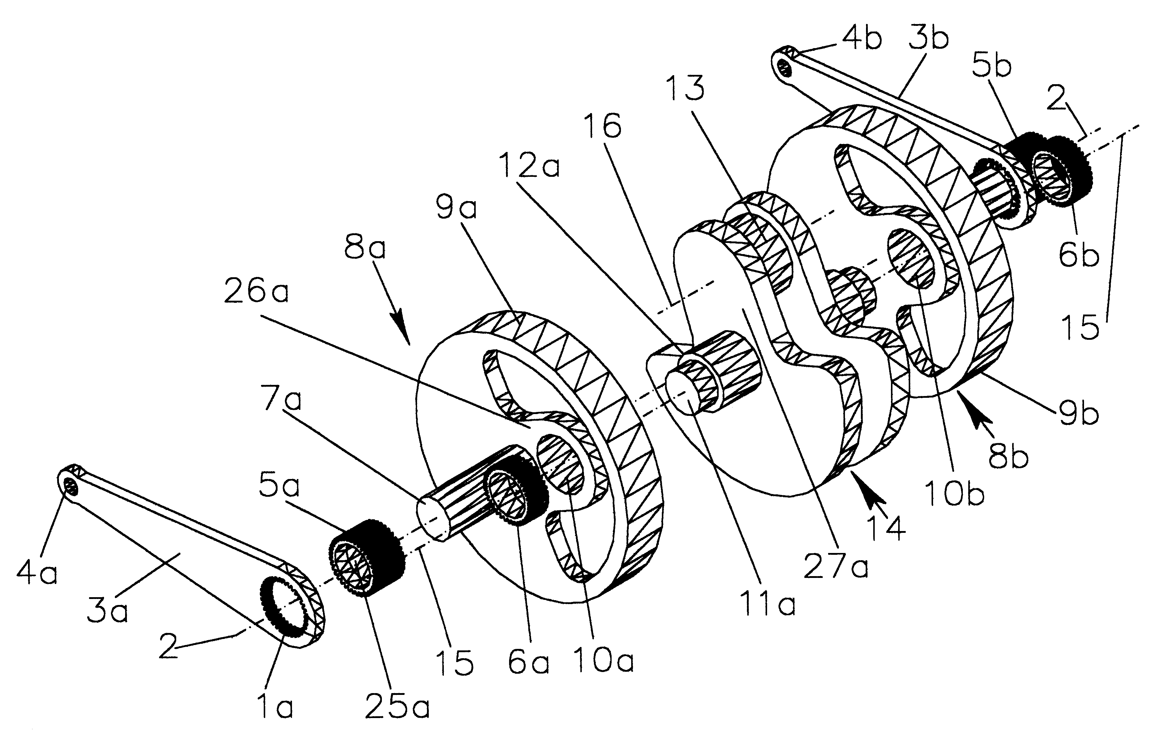
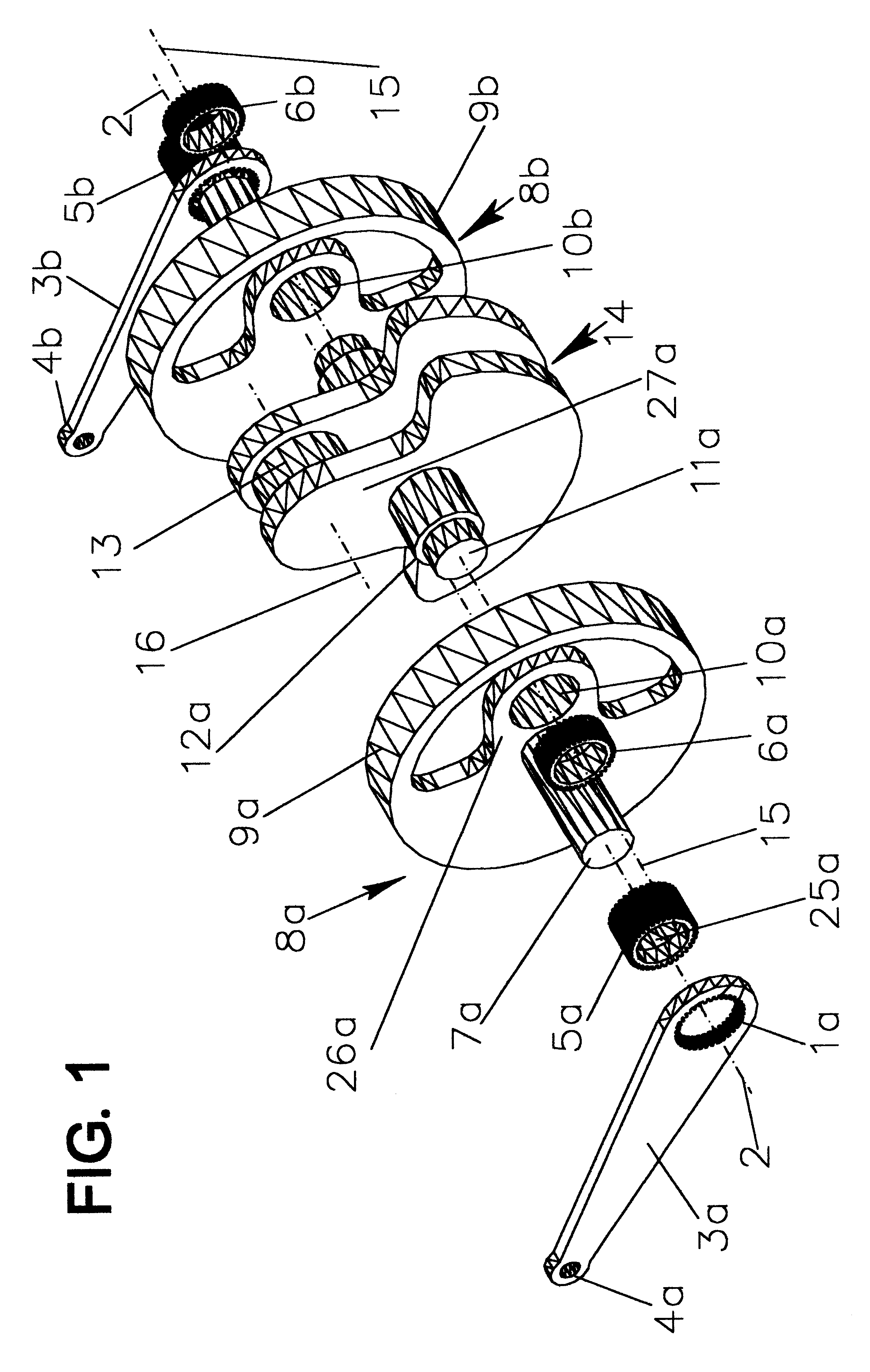
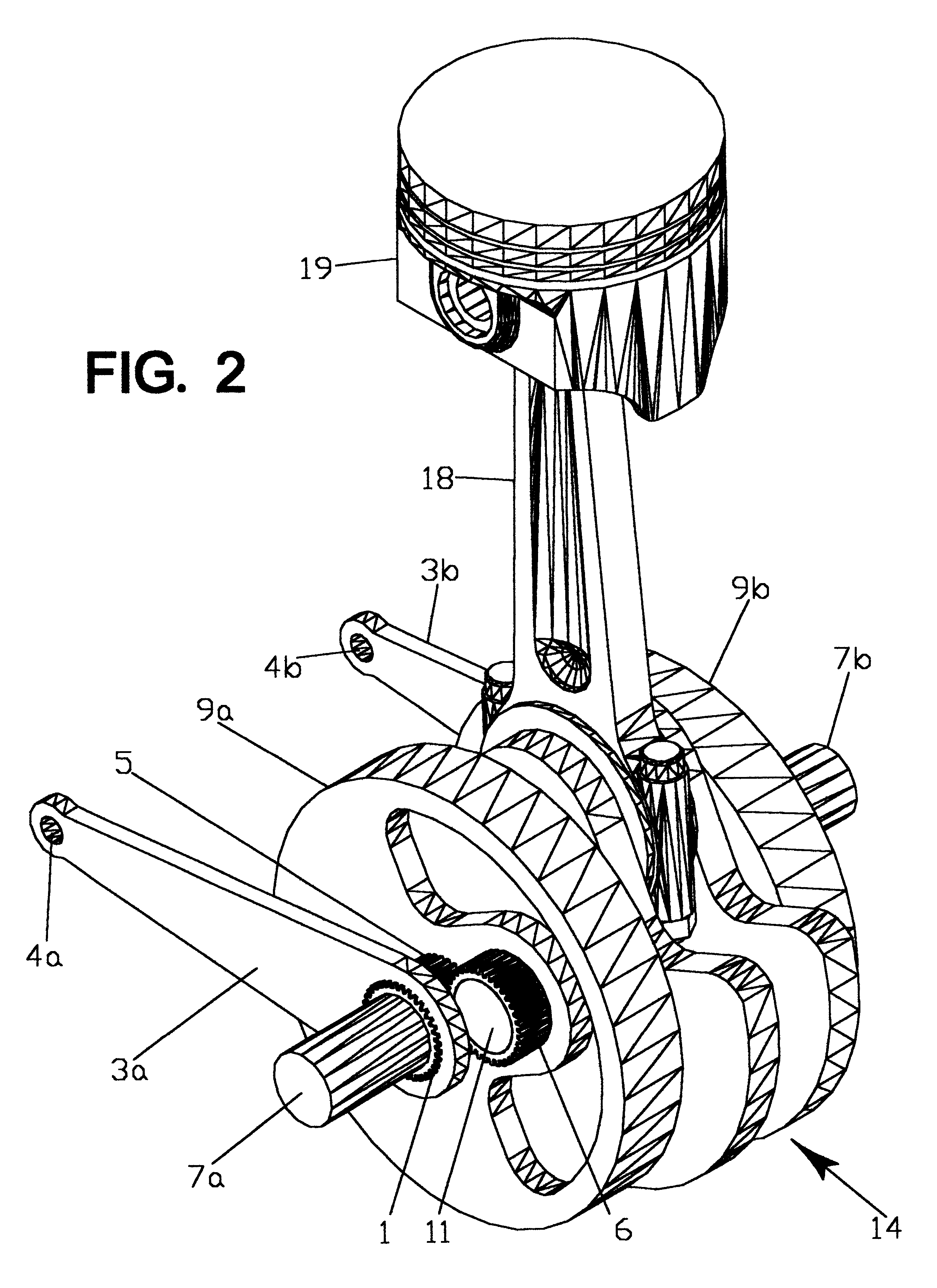
The previous embodiment described this invention in simple form to facilitate an understanding of the specifications and drawings. That embodiment is adequate for the types of engines referred to in the previous paragraph. For higher torque multi-cylinder engines of intermediate displacement a preferred embodiment offers increased strength and durability. The preferred embodiment provides an additional disc per mainshaft segment, describes the bearings, replaces the sun gear with a ring gear, adds a two gear set to return the journalshaft to a 1:1 ratio in the original direction of rotation and augments the drive means between mainshaft segments. The adjustment levers are replaced with external gear segments on the ring gears, although levers or any other adjustment means can be used. In FIGS. 14 and 15 the connecting rod 18 and piston 19 assemblies are identical with those of the simple embodiment. The journalshaft 114 differs only in length and the bearing and gear mounting of the...


PUM


Abstract

The cardioid cycle engine utilizes a centrally located output shaft which carries an orbiting crankshaft for each cylinder. The journals of the orbiting crankshafts trace a heart shaped pattern, hence the term "cardioid" cycle. The crankshafts are geared to rotate within the revolving output shaft in the same direction and at the same angular velocity as the output shaft. in the preferred embodiments the offsets of the two shafts are adjusted so that they are additive in the second quadrant of output shaft rotation. This configuration produces four strokes, variable in length and duration, in each 360° of output shaft rotation. The expansion stroke can exceed twice the intake stroke in length, and TDC can occur when the output shaft is well past the normal TDC position, allowing tangential force on the shaft when cylinder pressure is highest. Compression ratios can be varied over the full useable range while the engine is operating. When used as an engine, fuel efficiency and torque are increased, and when used as a compressor the peak torque loads are reduced.

Description

Not ApplicableNot ApplicableREFERENCE TO SEQUENCE LISTING OR APPENDIXNot ApplicableThis invention relates to variations in the rotating assemblies which alter the motion of the piston in internal combustion engines and similar machines.Since internal combustion engines were called "explosion engines" in the late 19th century there has been a continual quest to improve upon the purely sinusoidal curve generated by the crankpin, and therefore the piston in the theoretical case of an infinite rod length, of the simple, reliable and relatively inexpensive configuration used almost exclusively from that period through the entire 20th century.Some of the earliest inventions sought to provide complete scavenging of the cylinder on the exhaust stroke. Otto cycle engines were limited to compression ratios as low as 3:1 by the quality of the gasolines available, and some even burned the gaseous products of incomplete combustion of coal or wood. These dimensions would result in the dilution of...

Claims


Application Information

Patent Timeline
Patent Type & Authority Patents(United States)
IPC IPC(8): F02B75/32
CPCF02B75/32
Inventor SHAW, RALPH
Owner SHAW RALPH
Learn More