
Solenoid valve with a manual control pushbutton

Inactive Publication Date: 2003-03-04
PARKER HANNIFIN MFG FRANCE
View PDF22 Cites 9 Cited by
  • Summary
  • Abstract
  • Description
  • Claims
  • Application Information

AI Technical Summary

Benefits of technology

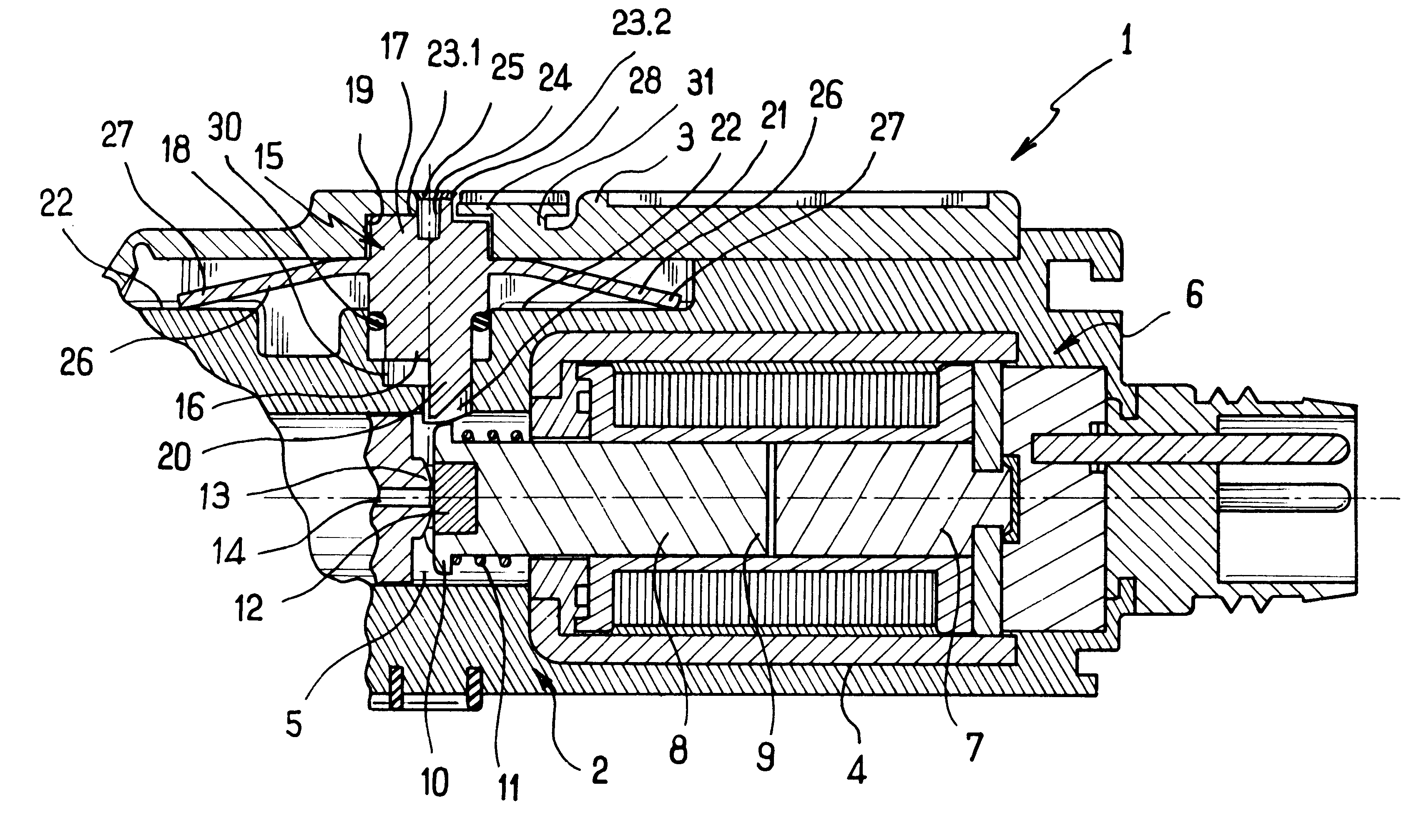
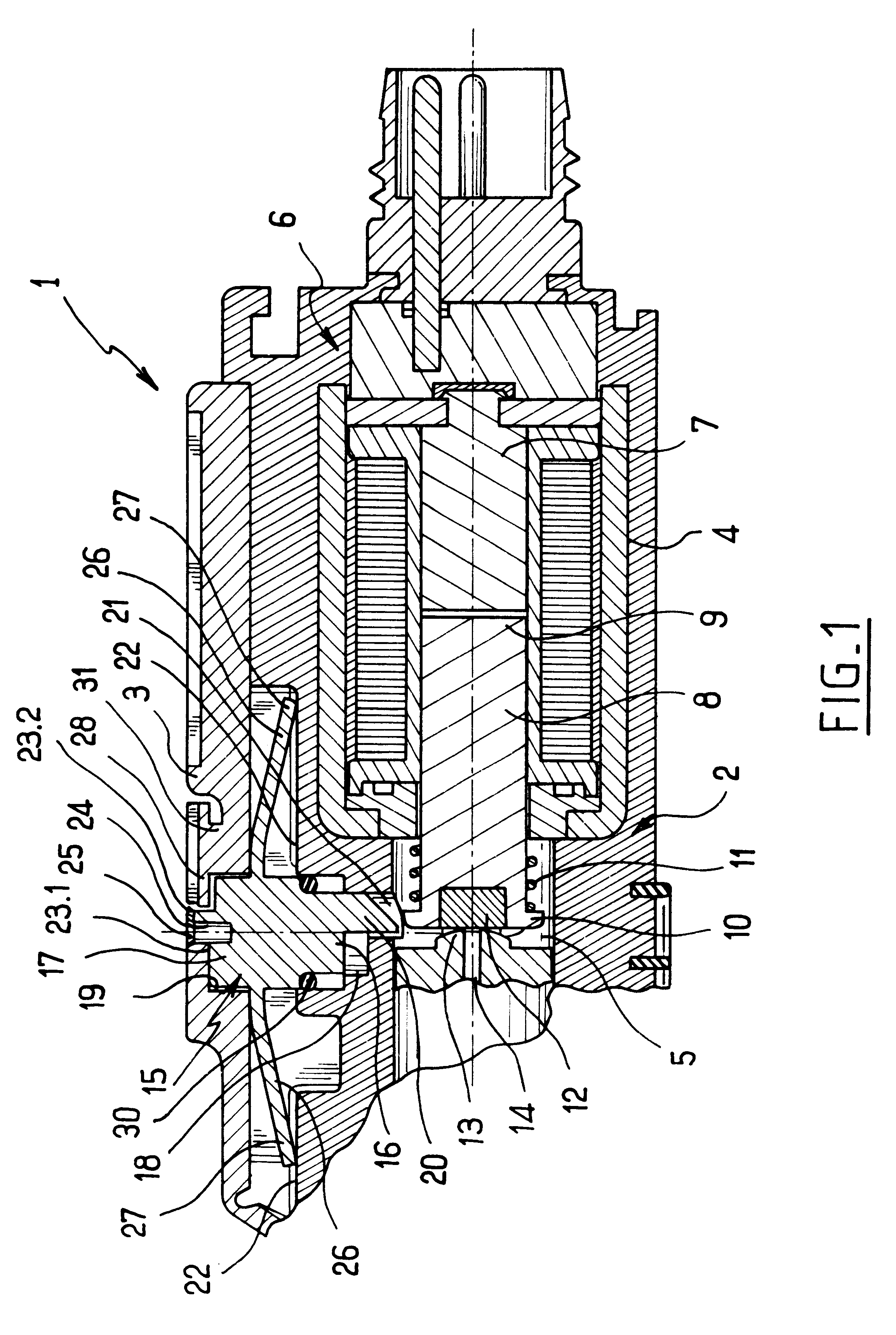
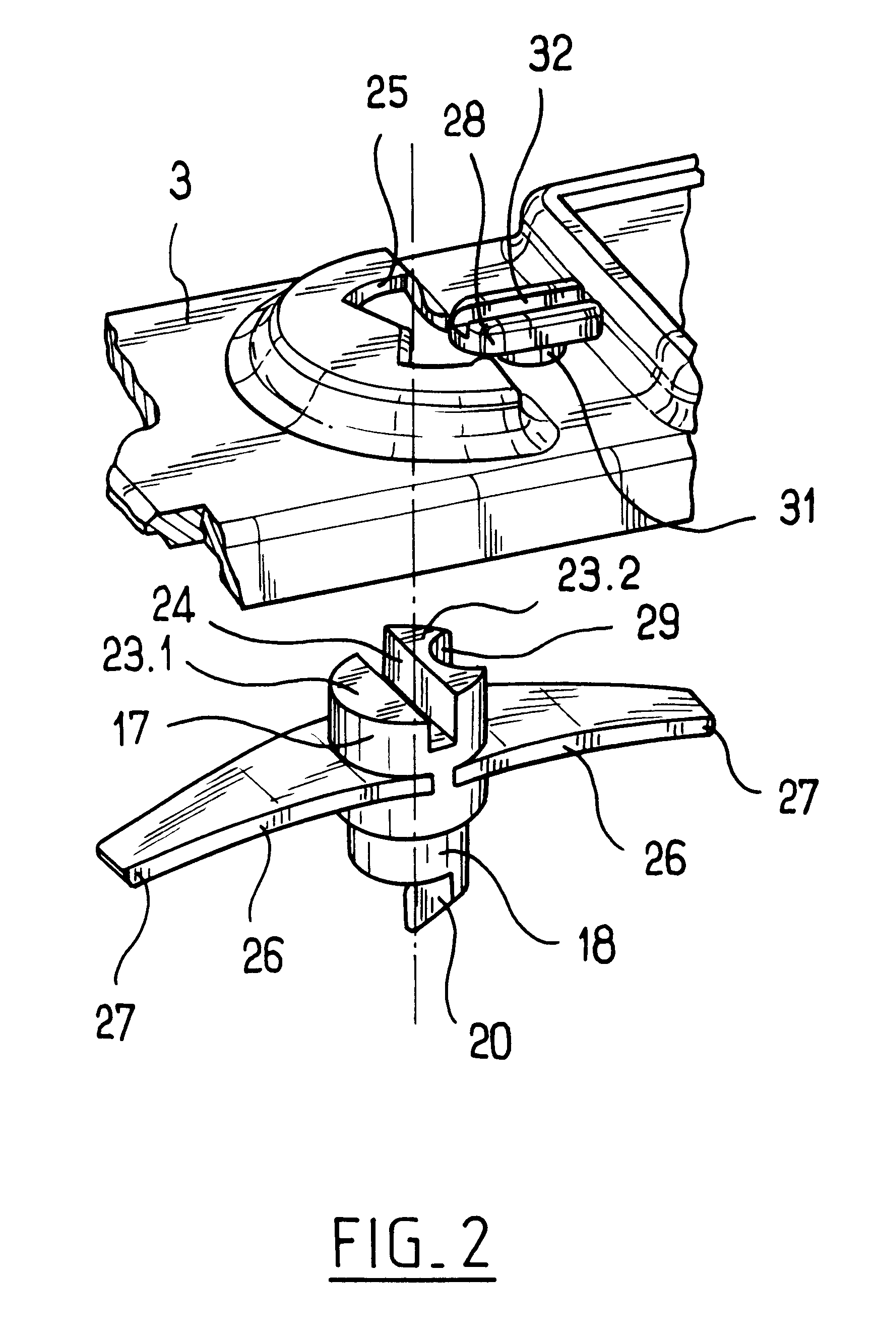
When the abutment element is in place, the pushbutton can be locked in the active position like a bayonet pushbutton. The solenoid valve is then adapted to be used with monostable directional control valves or to satisfy users of a certain type. When the abutment element is withdrawn, the pushbutton cannot be locked in the active position and it operates like a simple pushbutton. The solenoid valve is then adapted to be used with bistable directional control valves or to satisfy other users. The solenoid valve is thus adapted to the type of directional control valve that it is to control in a manner that is particularly simple, either by leaving the abutment element for the manual control pushbutton in place or by withdrawing it. Furthermore, by means of this disposition, a solenoid valve is made available whose control can be lockable during an initial stage of use (machine being set up by specialized personnel) and which is no longer lockable for subsequent use (e.g. during normal operation of the machine) where the personnel is less specialized.
Advantageously, the abutment element is fixed to the body in a zone thereof which is accessible from the outside. The abutment element can then be withdrawn without any need to disassemble the valve, and it can be withdrawn quickly.
In a particular embodiment, the releasable fixing means comprise a breakable tab which is preferably arranged to break in twisting, the abutment element having an indentation suitable for co-operating with a screwdriver type tool. Withdrawal of the abutment element is then irreversible. Furthermore, the abutment element can be made integrally with the body, thus simplifying the structure of the valve and making it easier to manufacture.

Problems solved by technology

There thus exists a need that has not been resolved in satisfactory manner at present for a single manual control means for a solenoid valve which is simple to adapt as a function of the intended purpose of the valve on which it is mounted.

Method used


Image

  • Solenoid valve with a manual control pushbutton
  • Solenoid valve with a manual control pushbutton
  • Solenoid valve with a manual control pushbutton

Examples


Embodiment Construction

The solenoid valve shown in the figures comprises a body given overall reference 1, made of a thermoplastic material and comprising a hollow-main portion 2 and a top cap 3 mounted on the main portion 2. The main portion 2 comprises two sections 4 and 5.

A first section 4 is overmolded on a solenoid or electromagnet given overall reference 6, comprising a frame, a coil, and a yoke 7.

In known manner, the electromagnet 6 possess a plunger core 8 which is slidably mounted in a cylindrical housing extending the yoke 7 and through an opening in the frame so as to have one end 9 adjacent to the yoke 7 and an opposite end 10 extending outside the frame. A spring 11 extends around the plunger core 8 between an end shoulder 10 and the frame, and it urges the plunger core 8 away from the yoke 7 in the absence of excitation. When the electromagnet 6 is excited, the magnetic forces involved overcome the effect of the spring 11 and press the end 9 of the plunger core 8 against the end wall of the ...


PUM


Abstract

A solenoid valve comprising a body in which there is fixed an electromagnet having a plunger core carrying at least one valve member and movable between first and second positions corresponding respectively to an excited state and to a rest state of the electromagnet, and a manual control pushbutton mounted on the body transversely to the plunger core firstly to slide between an active position in which a cam-forming end of the pushbutton co-operates with the plunger core to bring it into its first position and an inactive position into which the pushbutton is returned resiliently and its cam-forming end is disengaged from the plunger core, and secondly, while in the active position, to pivot between a locked position in which the pushbutton co-operates with an abutment element secured to the body which opposes resilient return, and an unlocked position in which the pushbutton escapes from the abutment element, the abutment element including means enabling it to be releasably fixed to the body.

Description

The present invention relates to a solenoid valve (an electrically-controlled pneumatic valve), e.g. for controlling directional control valves in pneumatic systems.In general, conventional types of solenoid valve comprise, in the most simple configuration, a body having a solenoid or electromagnet fixed therein with a plunger core carrying a valve member so as to move the valve member between a first position corresponding to an excited state of the electromagnet in which the valve member is spaced apart from its seat and puts two ducts into communication, and a second position corresponding to a non-excited state of the electromagnet in which the valve member is pressed against its seat and isolates the ducts from each other. Naturally, other types of solenoid valve also exist (e.g. having three ports and two positions) which, depending on the position of the valve member(s) serve to put one of two ducts selectively into communication with a third duct while isolating the other du...

Claims


Application Information

Patent Timeline
IPC IPC(8): F16K31/06H01F7/16H01F7/08F16K31/11F16K35/00
CPCH01F7/1607F16K31/0658
Inventor MULLER, PATRICK
Owner PARKER HANNIFIN MFG FRANCE
Learn More