Method and apparatus for expansion sealing concentric tubular structures

a technology of concentric tubular structures and sealing methods, applied in the direction of hose connections, cable terminations, borehole/well accessories, etc., can solve the problems of complex mechanisms, heavy structure, and failure to meet the requirements of the environment, and achieve the failure of complex mechanisms and the development of structurally heavy mechanisms for the placement of casing seals

Inactive Publication Date: 2003-03-11
BAILEY GARY L +1
View PDF35 Cites 130 Cited by
  • Summary
  • Abstract
  • Description
  • Claims
  • Application Information

AI Technical Summary

Benefits of technology

It is an object of the present invention to provide a packing type device for the placement, positioning and sealing of tubular members in a permanent manner that resists degradation of the seal over time.
It is an object of the present invention to provide a packing type device for the placement, positioning and sealing of tubular members in a permanent manner that resists degradation of the seal when exposed to high temperature and high pressure environments.
It is a further object of the present invention to provide a sealing system for use between concentric tubular members that seals the annular space between the tubular members and fixes the position of the tubular members with respect to each other, with a seal that retains its resiliency or internal pressure over time.
It is a further object of the present invention to provide a sealing device that may be moved to a position within an outer tubular member without significant damage to the surface area associated with the seal during the placement process.
It is a further object of the present invention to provide a seal placement method that may be implemented from a remote location but which involves a mechanical simplicity that reduces the likelihood of operational failure.
It is a further object of the present invention to provide a method for the placement of a seal between tubular members that requires only a simple structural linkage between the point of seal placement and the point from which the operation of the process is directed.

Problems solved by technology

One result dictated by some of the various factors mentioned above has been the development of structurally heavy and complex mechanisms for the placement of a casing seal especially those intended to be removable.
Complexity, however, leads to unreliability and failure which, if occurring many thousands of feet underground, can result in millions of dollars of recovery and retrieval costs.
Complexity also fails in environments where multiple seal placements are required.
The more complex the device the less it lends itself to reductions in size sufficient to permit such multiple seal placements.

Method used


Image

  • Method and apparatus for expansion sealing concentric tubular structures
  • Method and apparatus for expansion sealing concentric tubular structures
  • Method and apparatus for expansion sealing concentric tubular structures

Examples


Embodiment Construction

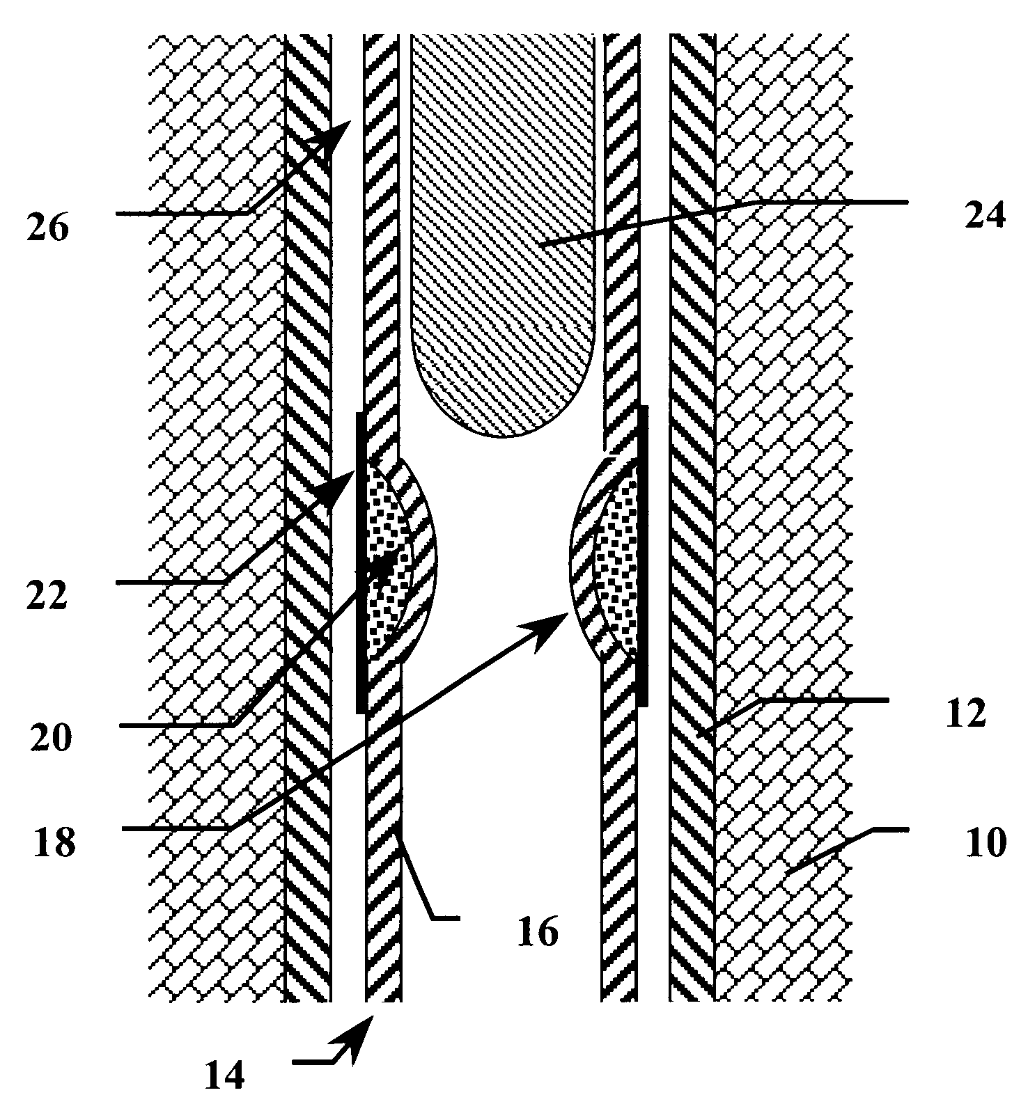
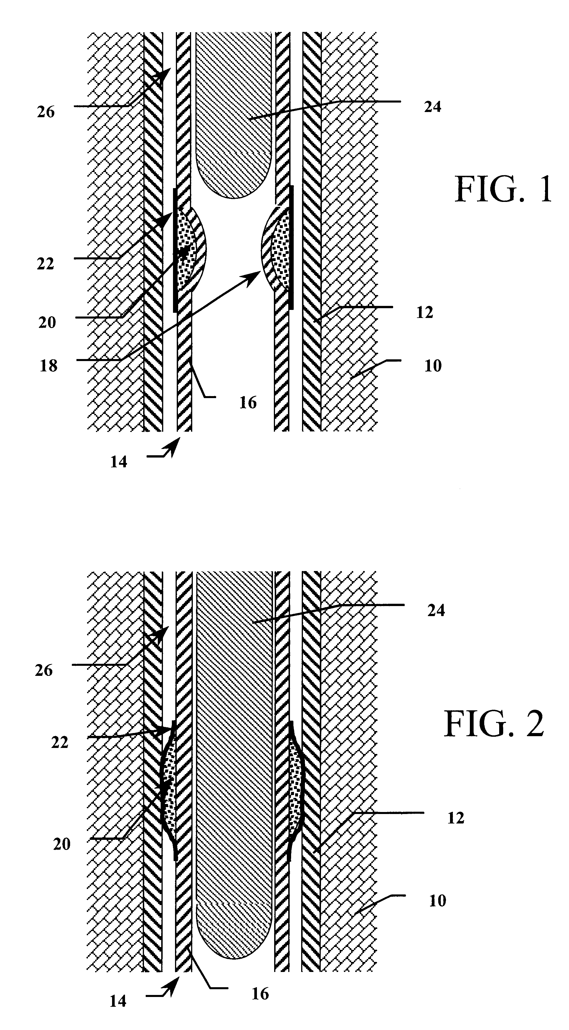
A key feature of the structure of the present invention as described above is the differential movement of the seal element made possible by the geometric design of the fluid storage area. The geometry allows the inner casing to be minimally deformed while still causing a large amount of expansion at the outer seal location. Long but shallow depressions can be used to store large amounts of deployment fluid. The only requirement to the geometry is that the sections of the inner tubular wall and the malleable / ductile cover sleeve be of sufficient strength to resist the hydrostatic pressure developed during deployment and operation of the seal element.

Reference is made to FIG. 7 for a detailed description of a preferred geometry to the depression formed within the inner tubular wall as described above. In FIG. 7 a detailed cross sectional view of inner tubular wall 16 is shown. Annular depression 18 is shown in cross section as well. Partially compressible fluid 20 is positioned withi...


PUM


Abstract

A device and method for sealing a first cylinder in a fixed position inside a second concentric cylinder. The inner cylinder has an annular depression in its wall at the point of sealant placement, which causes the wall of the inner cylinder to intrude inwardly. The depression is filled with a partially compressible fluid and is covered over by a malleable / ductile sleeve. The inner cylinder is placed within the outer cylinder with the covered annular depression positioned at the desired sealing point. A cylindrical displacement device is directed through the inside of the inner cylinder where it encounters the intrusion of the annular depression. The displacement device is forced past the annular intrusion and pushes the wall outward. The partially compressible fluid is forced to expand outward under the malleable / ductile cover in a manner that intrudes into the annular space between the inner cylinder and the outer cylinder and into contact with the outer cylinder. The partially compressible fluid has a residual energy sufficient to maintain the sealing element in contact with the outer cylinder.

Description

1. Field of the InventionThe present invention relates generally to methods and devices for positioning and sealing concentric tubular members with respect to each other. The present invention relates more specifically to methods and devices for creating differential movement and storing residual energy of sufficient volume and magnitude for hanging, sealing, or packing the annular space between a first tubular structure, such as a well casing, and a second tubular structure such as a pipe string.2. Description of the Related ArtThere are many environments within which concentric tubular elements are utilized to conduct the flow of various fluids and the like to and from fluid sources. Oil and gas well boreholes provide an example of one such environment. In many drilling operations it is desirable to provide casing within the well and to additionally segment or segregate portions of the cased borehole in order to access various formations encountered by the well. Segregation of a c...

Claims


Application Information

Patent Timeline
Patent Type & Authority Patents(United States)
IPC IPC(8): E21B33/12E21B43/02E21B43/10
CPCE21B33/1208E21B43/106E21B43/103
Inventor BAILEY, GARY L.WOODS, ROSS S.
Owner BAILEY GARY L
Why Eureka
Try Eureka