
Method and apparatus for measuring subcutaneous fat using ultrasonic wave

a technology of subcutaneous fat and ultrasonic wave, which is applied in the direction of ultrasonic/sonic/infrasonic image/data processing, application, ultrasonic/sonic/infrasonic diagnostics, etc., can solve the problems of large affecting the measurement result, the difficulty of properly selecting the part to be measured among the many parts of the person, and the defect of the prior art measuring process

Inactive Publication Date: 2003-03-11
TANITA CORP
View PDF6 Cites 78 Cited by
  • Summary
  • Abstract
  • Description
  • Claims
  • Application Information

AI Technical Summary

Problems solved by technology

Further, it is difficult to properly select the part to be measured among the many parts of the person as described above.
Therefore, the prior art measuring process is defective in that the measurement result is greatly affected by condition of the muscle.

Method used


Image

  • Method and apparatus for measuring subcutaneous fat using ultrasonic wave
  • Method and apparatus for measuring subcutaneous fat using ultrasonic wave
  • Method and apparatus for measuring subcutaneous fat using ultrasonic wave

Examples


first embodiment

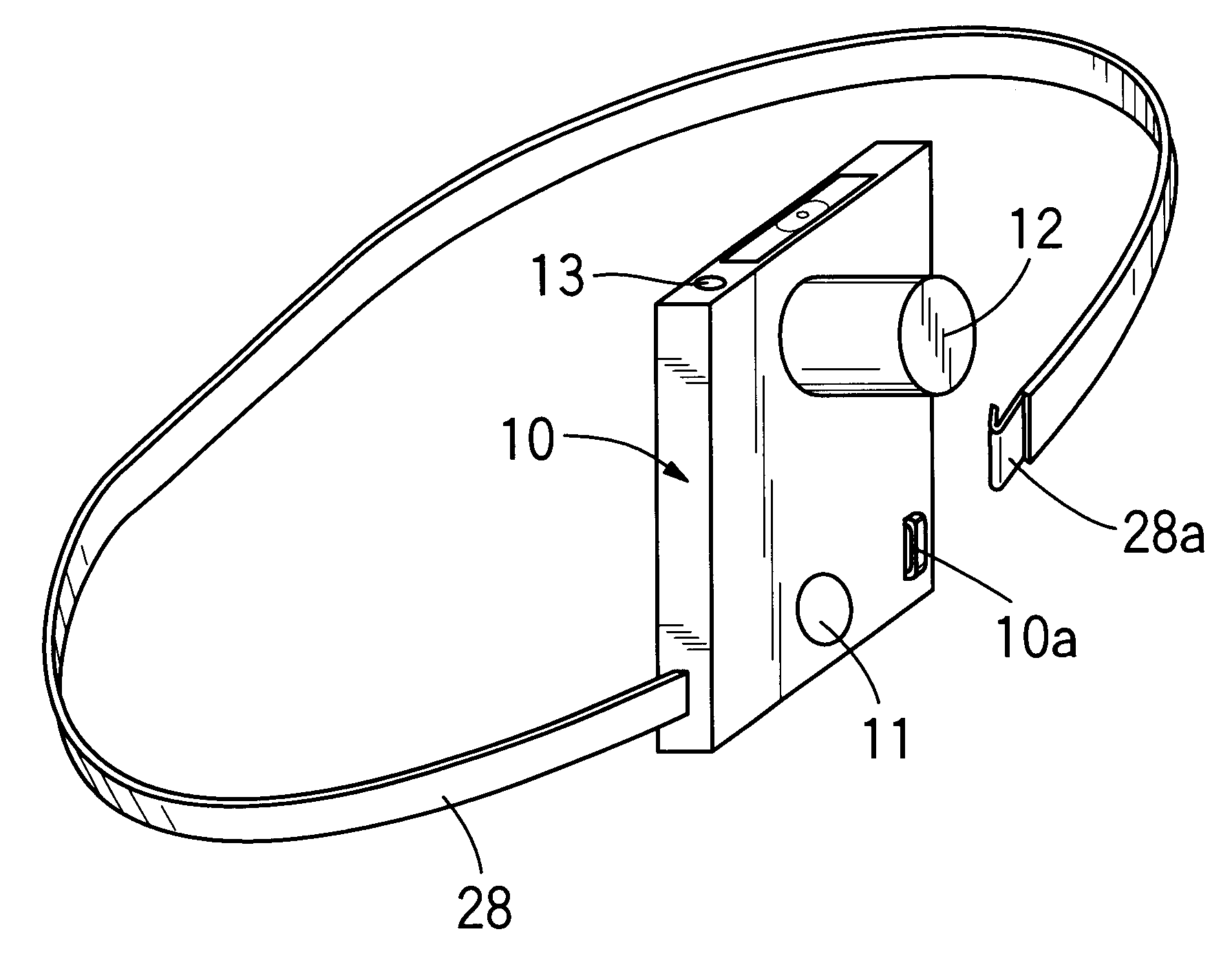
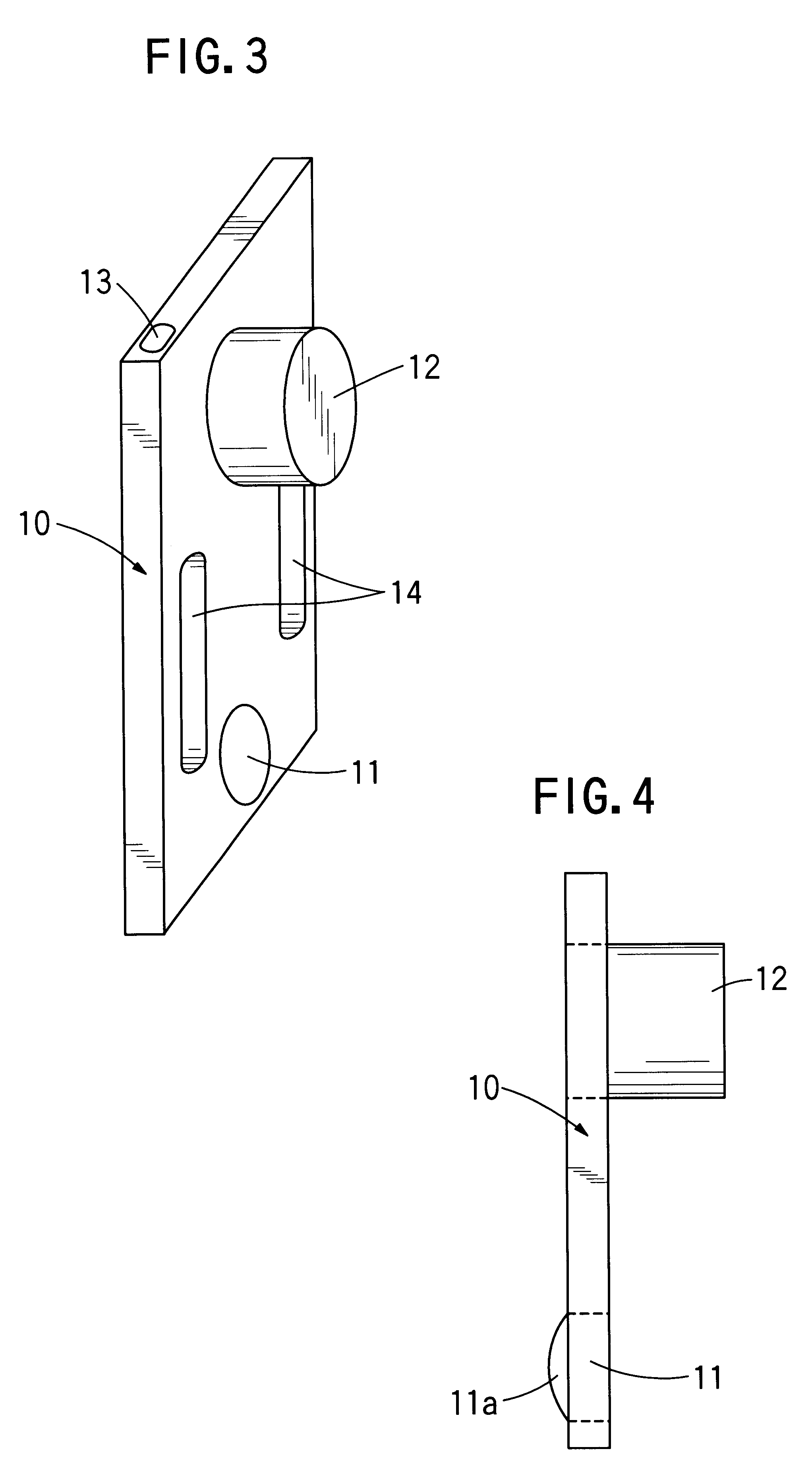
FIGS. 3 and 4 are perspective and side views each representing a subcutaneous fat measuring apparatus 10 according to the present invention. The subcutaneous fat measuring apparatus 10 includes a reference position setting device 11 for positioning the apparatus 10 by setting a projection 11a at the reference point or the navel 7 of a person under test. An ultrasonic probe 12 including an ultrasonic transmitter and an ultrasonic receiver is mounted on the apparatus 10 at the position above the reference position setting device 11. The ultrasonic probe 12 may be any one of the commercially available devices, and therefore, there is no need for detailed description of the probe 12. The measuring apparatus 10 includes a measurement start switch 13 mounted on the upper side thereof A person under test can operate the switch 13 by himself to start the measurement of subcutaneous fat thickness. The measuring apparatus 10 further includes belt holes 14 through which a belt is passed for fi...

second embodiment

FIG. 10 represents a measuring apparatus 36 for measuring the subcutaneous fat in an arm of the person according to the present invention. Reference numeral 30 represents a shoulder contact portion for making contact with a shoulder joint of the person, and 31 represents an elbow contact portion for making contact with an elbow joint of the person. The contact portions 30 and 31 are supported on support members 34 and 35 having rack portions 32 and 33 formed thereon, respectively. The support members 34 and 35 are movable to each other through a gear 37 sandwiched therebetween within the measuring apparatus 36. The measuring apparatus 36 includes an ultrasonic probe 38 at one side thereof and a measurement start switch 39 at the opposite side thereof. In operation of the apparatus 36, the shoulder contact portion 30 is put on the shoulder joint of the person and the elbow contact portion 31 is put on the elbow joint of the person while adjusting the interval between both contact por...


PUM


Abstract

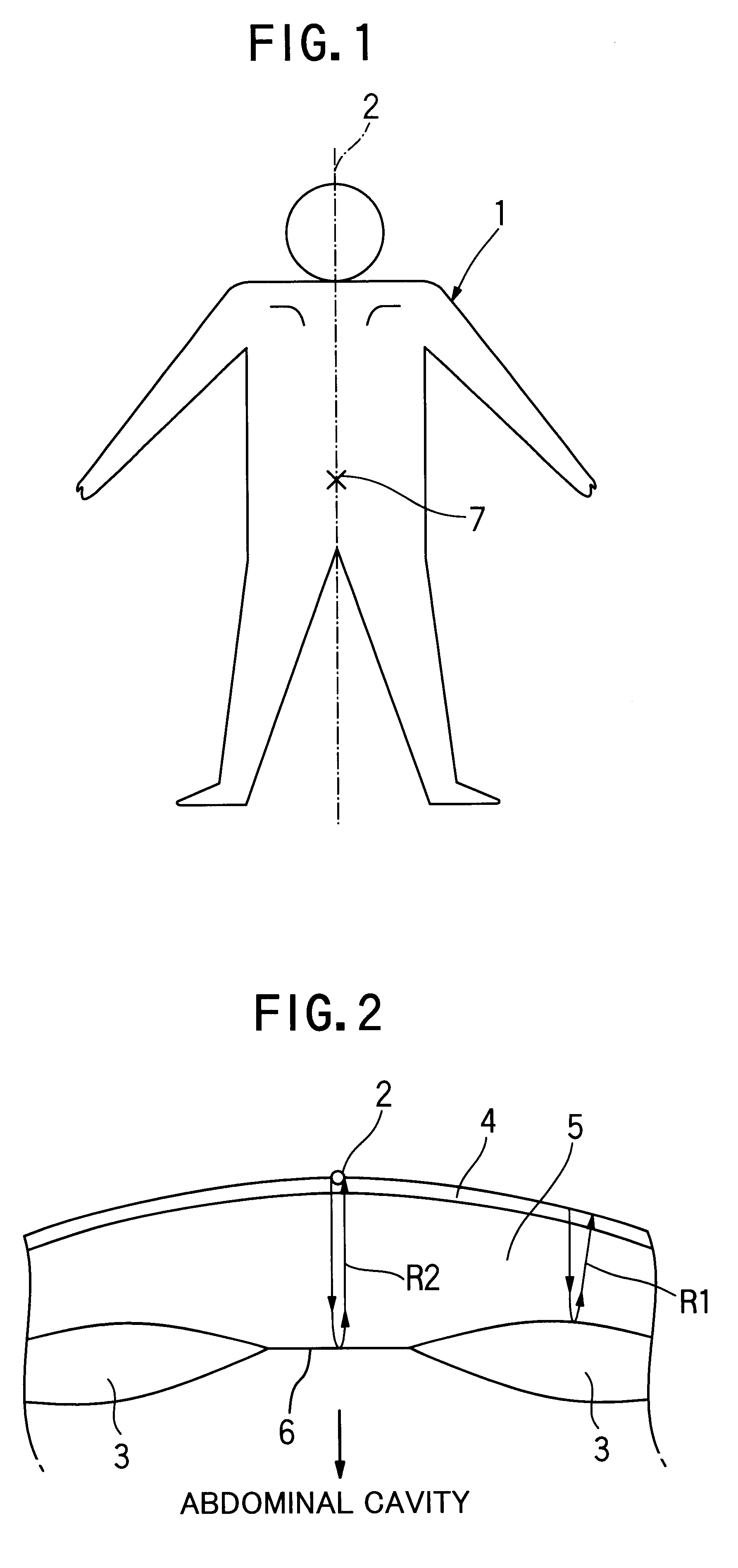
Disclosed is a method for measuring subcutaneous fat using an ultrasonic wave, comprising a step of measuring a portion of an abdomen on a median line of a person under test. The present invention also provides an apparatus for measuring subcutaneous fat using an ultrasonic wave. The apparatus comprises: a reference position setting device which sets said apparatus at a reference position for measurement on a person under test; an ultrasonic transmitter disposed at the predetermined position relative to said reference position setting device; and an ultrasonic receiver disposed at the predetermined position relative to said reference position setting device. According to the present invention, a navel of the person is defined as the reference position for measurement. The area to be measured on the abdomen of the person is located along the median line between the sternum and the pubis of the person. Furthermore, the ultrasonic transmitter and the ultrasonic receiver are disposed for measuring the subcutaneous fat in a position around 2 cm above the navel of the person along a median line.

Description

1. Field of the InventionThe present invention relates to a method and an apparatus for measuring subcutaneous fat using an ultrasonic wave.2. Description of the Prior ArtIn the past, the measurement of thickness of subcutaneous fat using an ultrasonic wave has been conducted only by physicians, practitioners and other skilled persons, based upon their experiences and according to manuals for measuring apparatus. And the measurement was generally performed at arbitrary selected parts or positions on a person under test, including those at the side of the navel, on the flank, on the back face of an upper arm and the like.In such prior art measuring process, an assistant person becomes necessary for performing the measurement, in addition to a person under test, depending on what part of the person is to be measured. Further, it is difficult to properly select the part to be measured among the many parts of the person as described above. It follows that the part to be measured may var...

Claims


Application Information

Patent Timeline
IPC IPC(8): A61B8/08
CPCA61B8/0858A61B5/4872
Inventor ISHIDA, HIDEAKISERITA, EIICHI
Owner TANITA CORP
Learn More