
Positive displacement pump

a technology of displacement pump and positive displacement, which is applied in the direction of positive displacement pump, machine/engine, piston pump, etc., can solve the problems of device not being able to operate against back pressure, liquid fertilizer additive is not kept constant, and the exact dimension of liquid fertilizer cannot be determined. , to achieve the effect of cheap and reliabl

Inactive Publication Date: 2003-03-18
WILLIAMS DAVID G
View PDF11 Cites 13 Cited by
  • Summary
  • Abstract
  • Description
  • Claims
  • Application Information

AI Technical Summary

Benefits of technology

to provide a cheap and reliable pump which delivers a steady stream of water / fertilizer mixture (or other mixture of liquids) of a constant concentration.
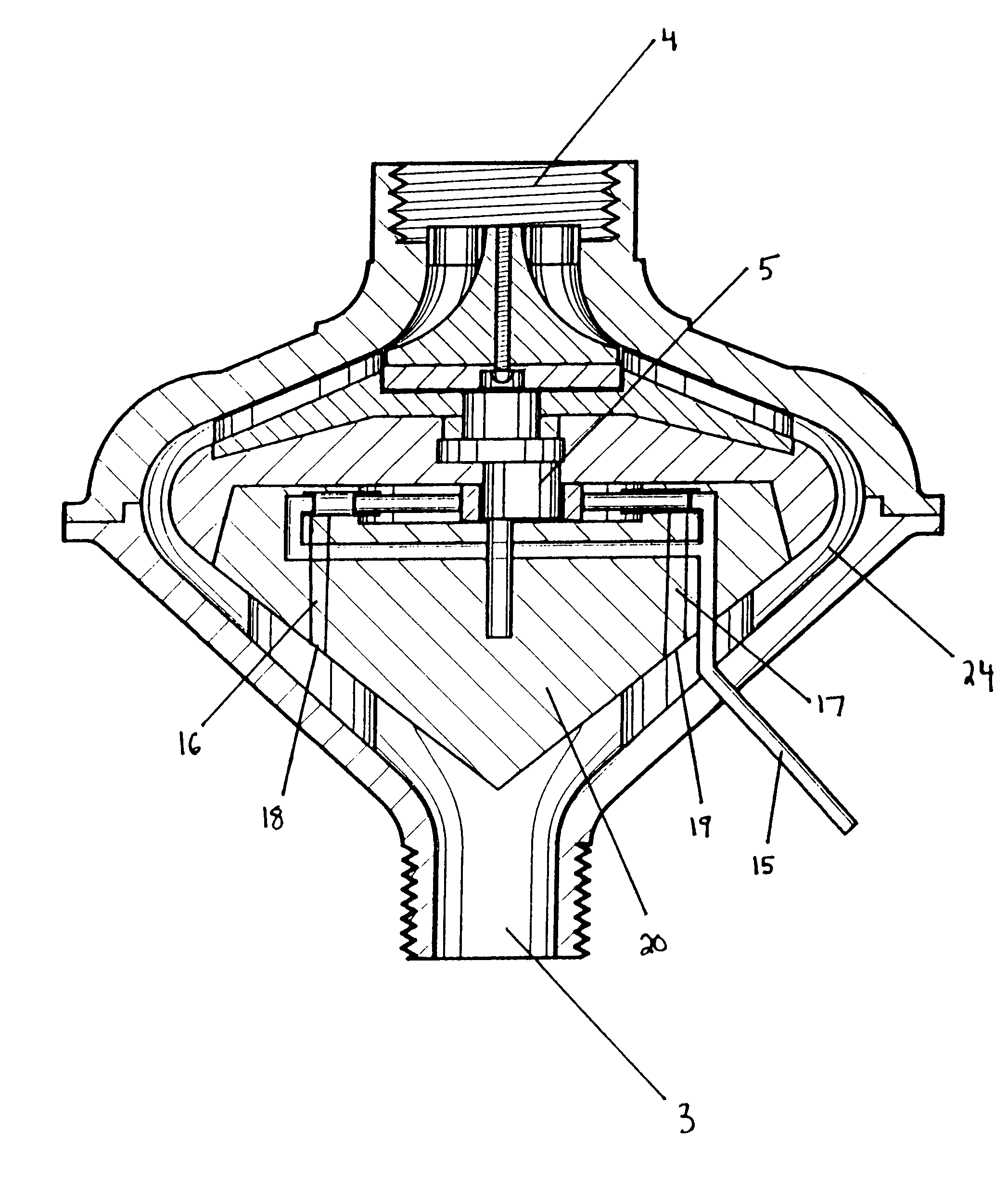
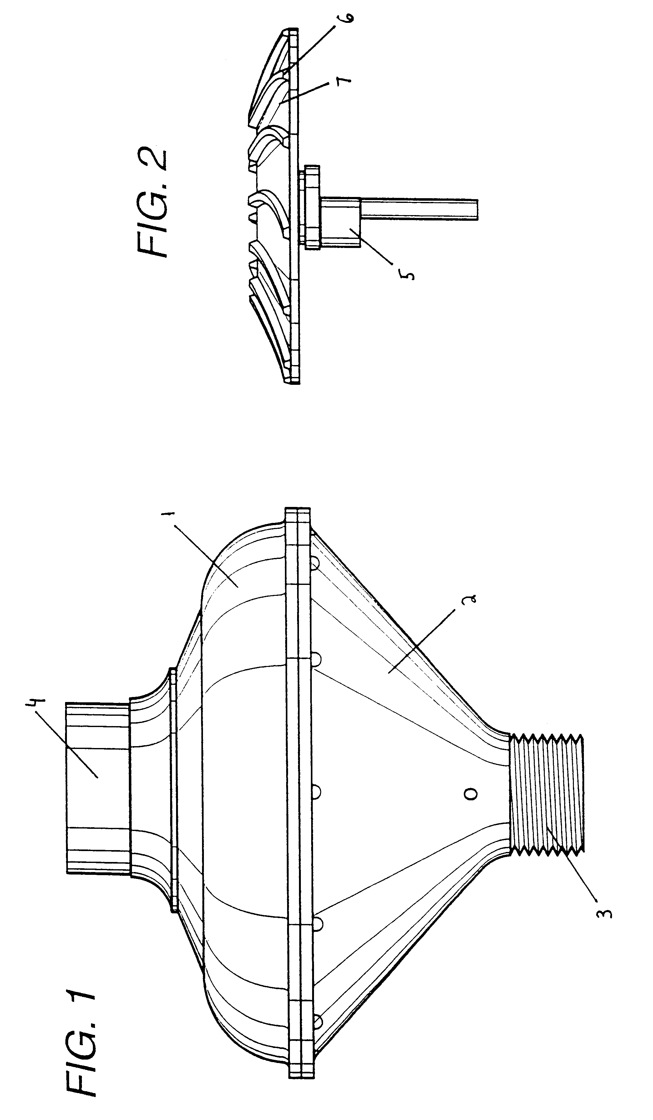
In general, the present invention involves a pump which can be connected to a faucet at its top end and connected to a typical garden hose or other device at its bottom end. Water enters the pump through a faucet and is redirected (bent) by vanes on a stator which allows the water to enter the turbine at an optimal angle to rotate the turbine impellers. The turbine is rotatably connected to a cam which allows the cam to move pistons. The movement of the pistons allows liquid fertilizer to be drawn from its reservoir when the valve connecting the liquid fertilizer reservoir to the pump is in an open position. The liquid fertilizer flows through an inlet tube into the piston and then into the exit tubes through the motion of the pistons. The liquid fertilizer combines with the water to create a water / fertilizer mixture which then flows through the hose to an attached sprinkler or other device.

Problems solved by technology

Unfortunately, such devices do not allow for exact dimensioning of liquid fertilizer into the water stream.
Often, the liquid fertilizer additive is not kept in a constant proportion to the irrigation water flow through the supply line.
Further, these devices cannot operate against back pressure which is created by a length of hose.
The main drawback of this system is the low efficiency of the helical pump due to its enclosure in a flexible stator housing causing considerable friction losses.
This system suffers from the drawback that the used water is spilled into the open, and that the pump-impeller is necessarily of low efficiency.
The main drawback of this embodiment is the requirement of bevel gearing for transmission of power from turbine to pump, which is usually a source of trouble, especially as the gear is submerged in the water in the pipe and is not readily accessible.
Obviously, the main drawback of this device is the requirement that a solid fertilizer be loaded into the casing prior to each use.

Method used


Image

  • Positive displacement pump
  • Positive displacement pump
  • Positive displacement pump

Examples


Embodiment Construction

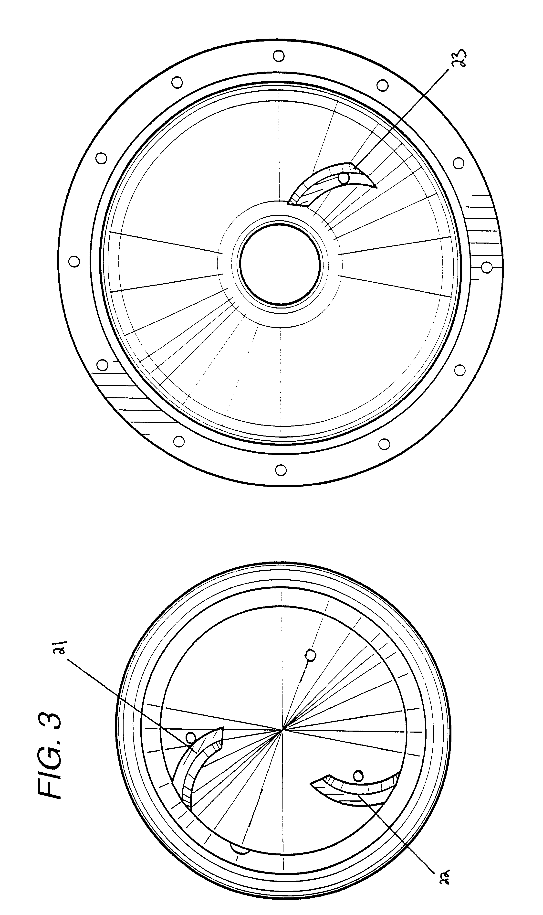
In the preferred embodiment of this invention, water which enters the pump through a faucet is redirected (bent) by ten stator vanes located in the entry passage (4) in the top portion of the pump. The water is bent as it travels through the channels of the upper stator vanes and into the channels (7) of the thirteen turbine vanes (6) which rotate around the upper stator. The water then spills out into a channel (24) between the bottom stator and the housing for the pump which causes the water to cascade down the side of the bottom stator (20). The motion of the turbine vanes (6) cause a one cylinder (crank shaft) cam (5) to spin because said cam (5) is rotatably connected at the center of the rotating turbine vanes (6). The cam (5) is surrounded by an oval ring (8) which is connected to two pistons (9 and 10). The rotation of the cam (5) causes the oval ring (8) to move laterally and to cause the dual positive displacement pistons (9 and 10) to pump. This pumping action allows liqu...


PUM


Abstract

This invention relates to a positive displacement pump which allows a liquid additive (such as liquid fertilizer) to be introduced into another liquid stream (such as water) and to be mixed in a constant proportion. One end of the pump can be connected to a faucet and the other end to a typical garden hose or other device. Water enters the pump through a faucet and is redirected (bent) by an upper stator which allows the water to rotate turbine vanes. The turbine is rotatably connected to a cam and the rotation of the cam moves pistons which allows liquid fertilizer to be drawn in from its reservoir. The liquid fertilizer flows through a tube and into one of two pistons. Then, the liquid fertilizer is dispelled through one of the exit tubes through the pumping action of the pistons. The water which was used to turn the turbine then combines with the liquid fertilizer as it comes out of the exit tubes and a water / fertilizer mixture is created.

Description

Not applicable.1. Field of the InventionThis invention relates to a positive displacement pump which allows a liquid additive to be introduced into another liquid stream (such as water coming from a faucet) and mixes the liquids together in a constant proportion without the use of any external power source.2. Description of the Related ArtThe prior art in this field contains many methods for injecting fertilizer or the like into a water stream. Some of these devices utilize an external power source to inject fertilizer into a water supply. Other pumps rely on small pressure drops in the lines to inject fertilizer. These are often referred to as Venturi-type injectors. Unfortunately, such devices do not allow for exact dimensioning of liquid fertilizer into the water stream. Often, the liquid fertilizer additive is not kept in a constant proportion to the irrigation water flow through the supply line. Further, these devices cannot operate against back pressure which is created by a l...

Claims


Application Information

Patent Timeline
Patent Type & Authority Patents(United States)
IPC IPC(8): A01C23/00A01C23/04B01F5/00B01F5/12F01D15/08F01D15/00F04B17/00B01F25/60
CPCA01C23/042F04B17/00F01D15/08B01F5/12Y10T137/479B01F25/60
Inventor WILLIAMS, DAVID G.
Owner WILLIAMS DAVID G
Learn More